Yaskawa SMC–4000 User Manual
Page 165
155
SMC–4000 User Manual
USAGE:
EXAMPLES:
This program was designed to read four analog inputs from 2 analog input cards (the first two cards) in
the rack of a Wago I/O system. Note Modbus function 3 is used to read the four regsiters starting at
register 0 (The E & R variables.) Register 0 correlates to Modbus address 40000. The data received is a
binary value that reporesents a +/- 10 volt input, thus the conversion calculation.
#TEST
DM WAGO[100]
WT 1000
IA 192,168,3,100; WT500; MW1
IHC=>-2
#WT; WT 50; JP#WT,_IHC2<>0
IHC=192,168,3,211<502>2
#WTHC; WT 50; JP #WTHC,_IHC2<>-2
E=0; R=4; i=0
#MAIN
MBC=3,3,E,R,WAGO[]
#MGLP
IF (WAGO[i]<$8000)
VOLTS=(WAGO[i]/$7FFF)*10
ELSE
VOLTS=(WAGO[i]-$10000)/$7FFF*10
ENDIF
MG VOLTS{$F2.4}," " {N}; i=i+1
JP #MGLP,i<R; i=0
MG; WT500
JP #MAIN
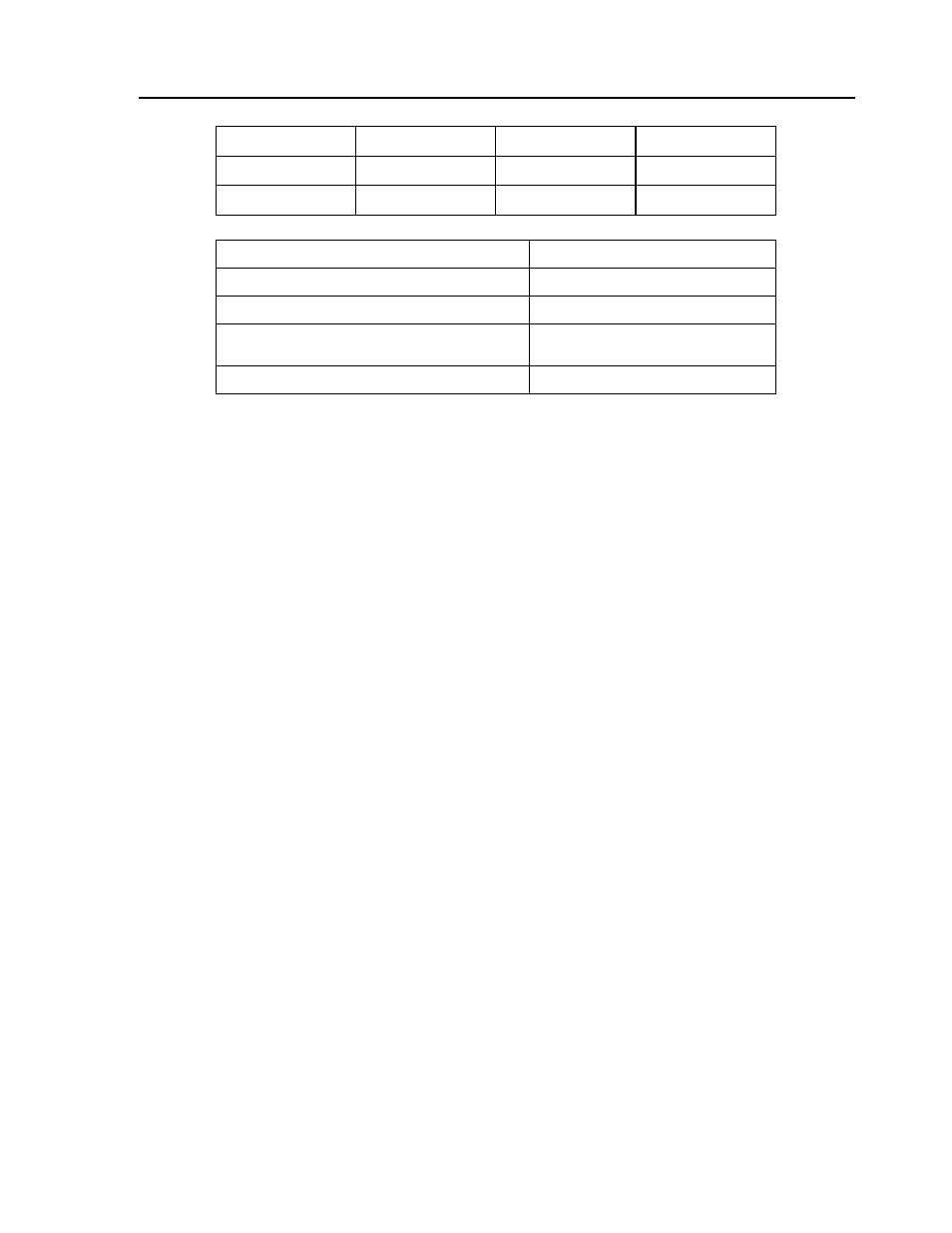
While Moving
Yes
Default Value
---
In a Program
Yes
Default Format
---
Command Line
Yes
IHF=>-2
Disconnect handle
IHF=192,168,3,11<502>2
Connect handle
MBF=6,16,632+(MODULE*8),NUMOFIO*2,A[ ]
Send Modbus configuration command
MBF=6,6,1025,1
Modbus command to burn parameters in
OPTO-22 Ethernet module
MBF=6,2,0,1,A[ ]
Read single digital input into array A