Notch filter – Yaskawa SMC–4000 User Manual
Page 39
29
SMC–4000 User Manual
Assuming a sampling period of T=1ms, the parameters of the digital filter are:
KPX = 20.6
KDX = 68.6
The SMC–4000 can be programmed with the instruction:
KP 20.6
KD 68.6
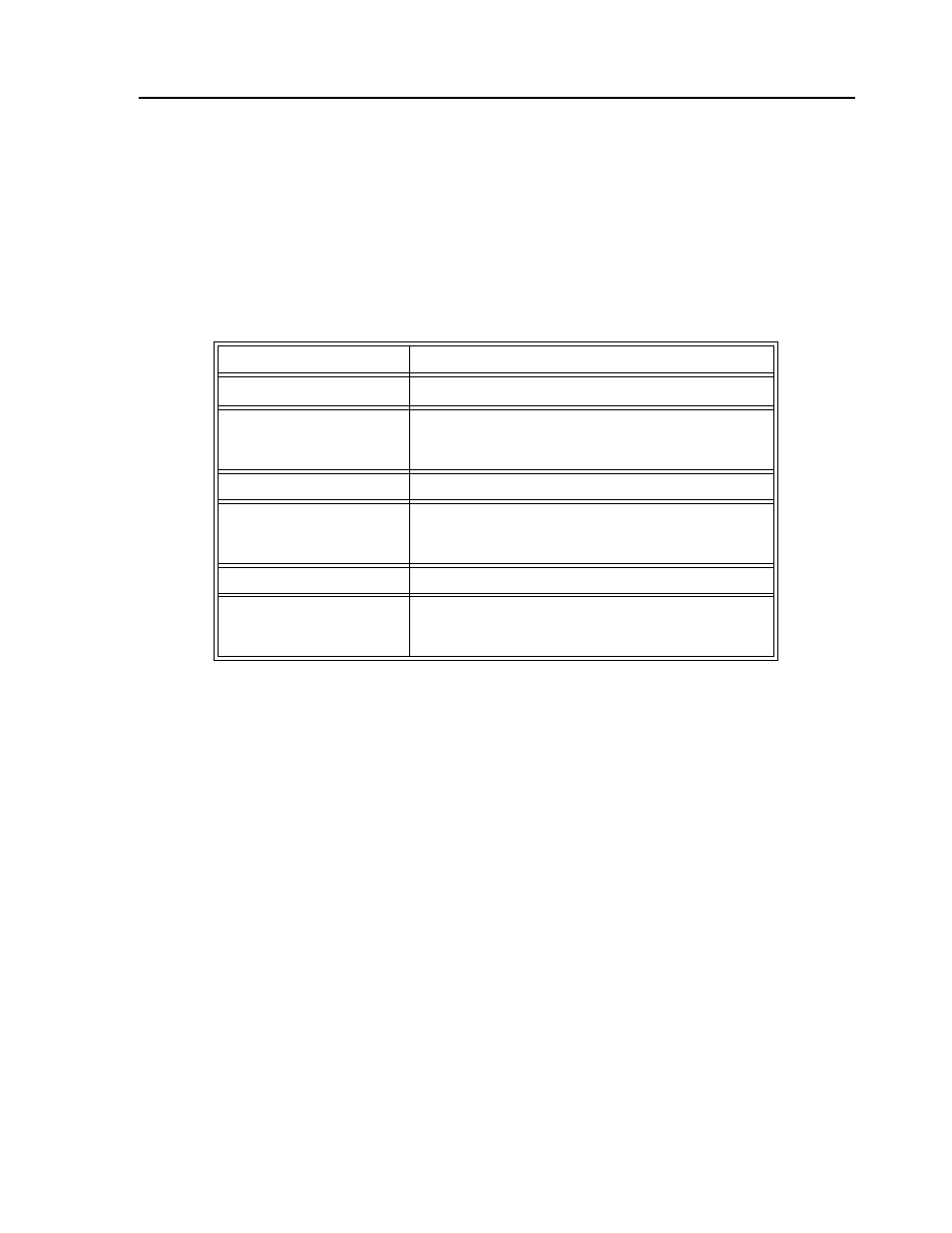
In a similar manner, other filters can be programmed. The procedure is simplified by the following table,
which summarizes the relationship between the various filters.
Notch Filter
There are some applications in which the standard tuning procedure using the PID filter of the controller
cannot completely eliminate the resonance in a system. Resonance occurs when the natural frequency of
a system is excited in a way that increases the amplitude of oscillation. This is usually due to system
compliance, such as a mechanical coupling or inherent motor characteristics.
The notch filter is an advanced tuning technique that acts much like a “band-reject” filter in an electronic
circuit. Certain frequencies are rejected while others are allowed to pass through. This is particularly
helpful when trying to eliminate a resonance that always occurs at a single frequency.
If a system oscillates at a specific point, then the first thing to do is find out at what frequency it occurs.
The easiest way to do this is to graph the Actual Motor Position versus Time while the motor is
oscillating. A sine wave with a constant frequency of oscillation should be seen. To get the frequency, f
(Hertz), count the number of peaks that occur in 1 second. Or alternatively, measure the distance between
two peaks, called the Period T (seconds), and then use the equation: f = 1/T.
Digital
D(z) = K(z-A/z) + Cz/z-1
Digital
D(z) = KP + KD(1-z
-1
) + KI/8(1-z
-1
)
KP, KD, KI
K = KP + KD
A = KD/(KP+KD)
C = KI/8
Digital
D(z) = GN(z-ZR)/z + KI z/8(z-1)
GN, ZR, KI
K = GN
A = ZR
C = KI/8
Continuous
G(s) = P + Ds + I/s
PID, T
P = K(1-A) = KP
D = K *A * T = T * KD
I = C/T = KI / 8 * TM