System modeling, Basic block diagram, Controller – Yaskawa SMC–4000 User Manual
Page 31: Motor-amplifier, Smc–4000 user manual, The motor amplifier is configured for current mode, Functional elements of a motion control system
Advertising
21
SMC–4000 User Manual
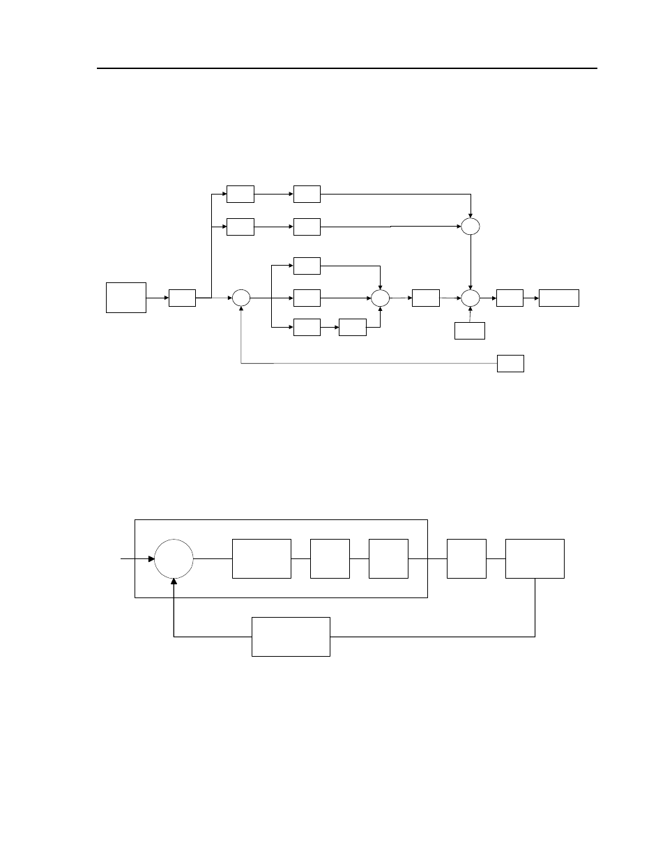
System Modeling
Basic Block Diagram
The elements of a servo system include the motor, driver, encoder and the controller. These elements are
shown in the following illustration. The mathematical model of the various components is given below:
Controller
Functional Elements of a Motion Control System
Motor-Amplifier
The motor amplifier is configured for current mode:
Motion
Generator
[PA][PR][SP][AC]
[DC][JG][IP]
Scurve
Smoothing
[IT]
Velocity
Feed Forward
[FV]
Acceleration
Feed Forward
[FA]
Proportional
Gain
[KP]
Derivative
Gain
[KD]
Integral
Gain
[KI]
Integrator
Limit
[IL]
Notch Filter
[NF] [NB] [NZ]
Torque Limit
[TL]
Offset
[OF]
Speed
Acceleration
+
+
+
+
+
+
+
Encoder
Feedback
-
+
+
D/A
To Legend Amp
DIGITAL
FILTER
Σ
ZOH
DAC
ENCODER
AMP
MOTOR
CONTROLLER
R
C
X
Y
V
E
P
Advertising