Yaskawa SMC–4000 User Manual
Page 42
32
SMC–4000 User Manual
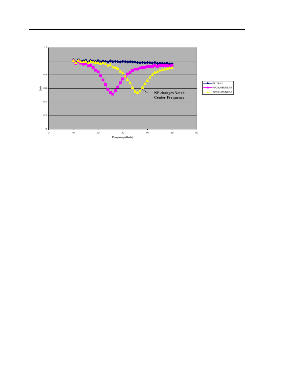
These graphs show how NF, NB, and NZ determine the characteristics of the filter. In particular, NB
specifies the bandwidth that is rejected (Figure 1). A larger NB causes a larger range of frequencies to be
attenuated. The ratio of NB/NZ controls the amount of attenuation, or depth of the notch (Figure 2). A
larger ratio causes a higher amount of attenuation. However, a ratio equal to one should have very little, or
no effect, on the output (Figure 3). A ratio greater than one will amplify the output signal (Figure 3)
causing a resonance. For consistency, these notch waveforms all have a center frequency of 25Hz, except
for the last one (Figure 4) which has a NF of 35 and is therefore shifted to the right.
A simple method for attaining your NF,NB, and NZ parameters is the following:
•Estimate resonance frequency.
•Set NF to resonance frequency in Hz.
•Set NB = 1/2 NF.
•Set NZ between zero and 5.
Although the theory behind a notch filter is beyond the scope of this application note, a general overview
may clarify how the notch works. As shown, the notch filter compensates for a resonance in the system.
One method of illustrating this is by looking at the poles and zeroes of the transfer function plotted on the
s-plane.