Ipv4 static route configuration example, Network requirements, Configuration outlines – H3C Technologies H3C WX3000E Series Wireless Switches User Manual
Page 183: Configuration procedure
167
Item Description
Interface
Select the outgoing interface.
You can select any available Layer 3 interface, for example, a virtual
interface, of the device. If you select NULL 0, the destination IPv6
address is unreachable.
IPv4 static route configuration example
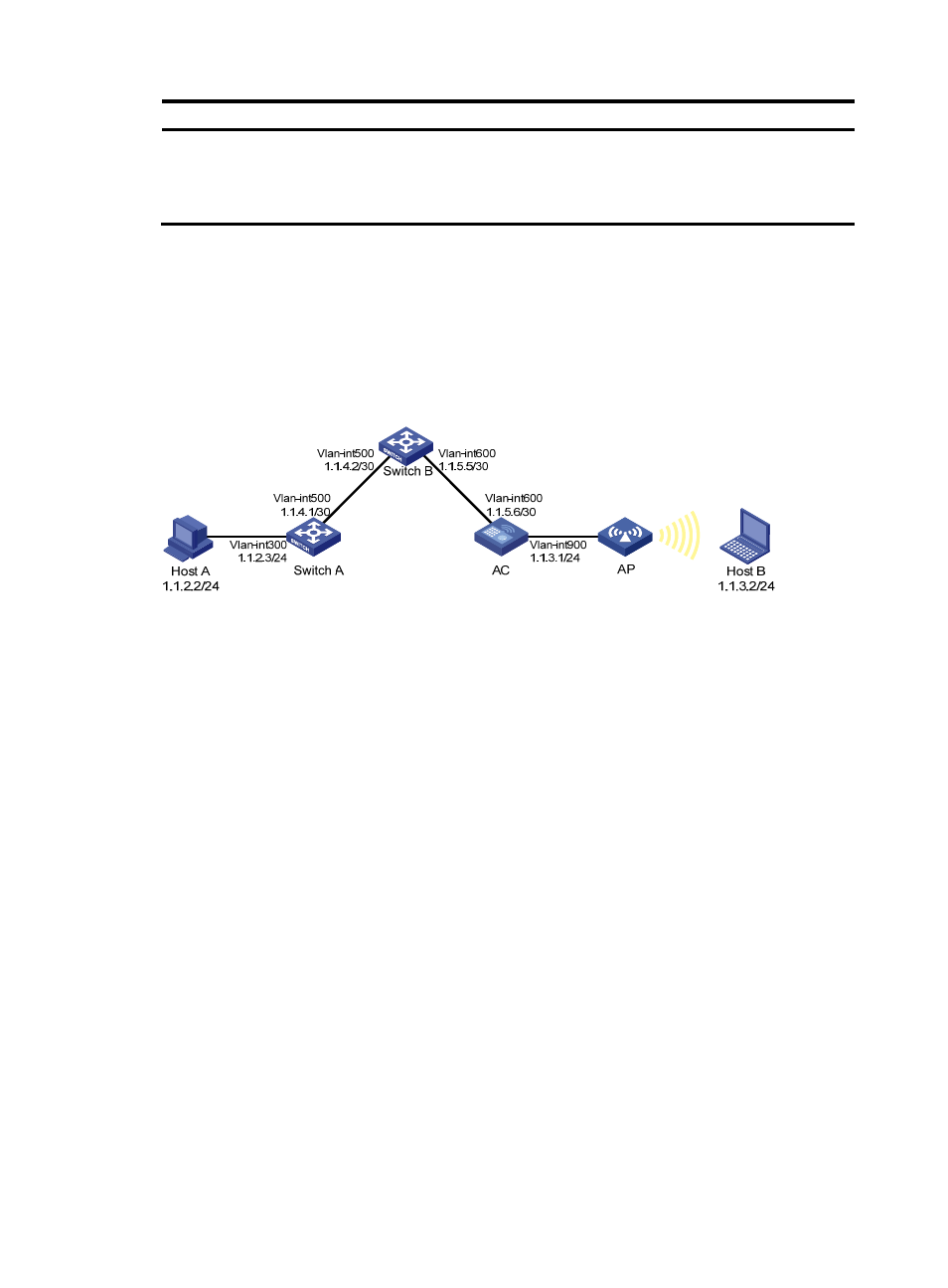
Network requirements
The IP addresses of devices are shown in
. IPv4 static routes must be configured on Switch A,
Switch B and AC for Host A and Host B to communicate with each other.
Figure 149 Network diagram
Configuration outlines
1.
On Switch A, configure a default route with Switch B as the next hop.
2.
On Switch B, configure one static route with Switch A as the next hop and the other with AC as the
next hop.
3.
On AC, configure a default route with Switch B as the next hop.
Configuration procedure
1.
Configure a default route with the next hop address 1.1.4.2 on Switch A.
2.
Configure two static routes on Switch B: one with destination address 1.1.2.0/24 and next hop
address 1.1.4.1, and the other with destination address 1.1.3.0/24 and next hop address
1.1.5.6.
3.
Configure a default route on AC:
a.
Select Network > IPv4 Routing from the navigation tree.
b.
Click the Create tab to enter the IPv4 static route configuration page, as shown in
c.
Enter 0.0.0.0 for Destination IP Address, 0 for Mask, and 1.1.5.5 for Next Hop.
d.
Click Apply.