Fundamentals of path functions 6.2 – HEIDENHAIN TNC 620 (81760x-02) ISO programming User Manual
Page 203
Fundamentals of path functions
6.2
6
TNC 620 | User's ManualDIN/ISO Programming | 2/2015
203
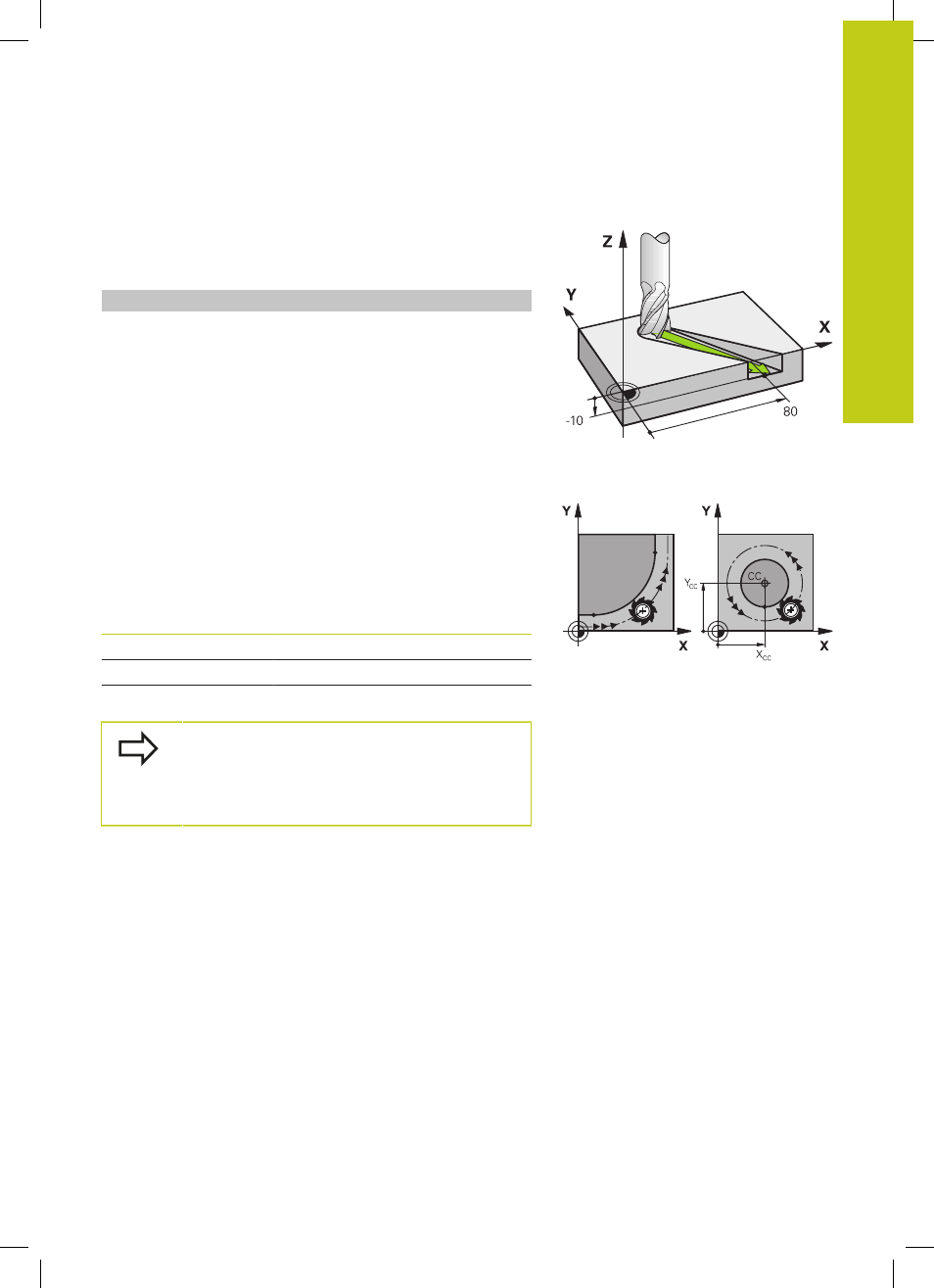
Three-dimensional movement
The program block contains three coordinates. The TNC thus
moves the tool in space to the programmed position.
Example
N50 G01 X+80 Y+0 Z-10 *
Circles and circular arcs
The TNC moves two axes simultaneously on a circular path relative
to the workpiece. You can define a circular movement by entering
the circle center with
I and J.
When you program a circle, the control assigns it to one of the
main planes. This plane is defined automatically when you set the
spindle axis during a
T:
Spindle axis
Main plane
(G17)
XY, also UV, XV, UY
(G18)
ZX, also WU, ZU, WX
(G19)
YZ, also VW, YW, VZ
You can program circles that do not lie parallel
to a main plane by using the function for tilting
the working plane (see User's Manual for Cycles,
Cycle 19, WORKING PLANE) or Q parameters (see
"Principle and overview of functions", page 290).
Direction of rotation DR for circular movements
When a circular path has no tangential transition to another contour
element, enter the direction of rotation as follows:
Clockwise direction of rotation:
G02/G12
Counterclockwise direction of rotation:
G03/G13