Reference system on milling machines, Designation of the axes on milling machines, Fundamentals 3.1 – HEIDENHAIN TNC 620 (81760x-02) ISO programming User Manual
Page 93
Fundamentals
3.1
3
TNC 620 | User's ManualDIN/ISO Programming | 2/2015
93
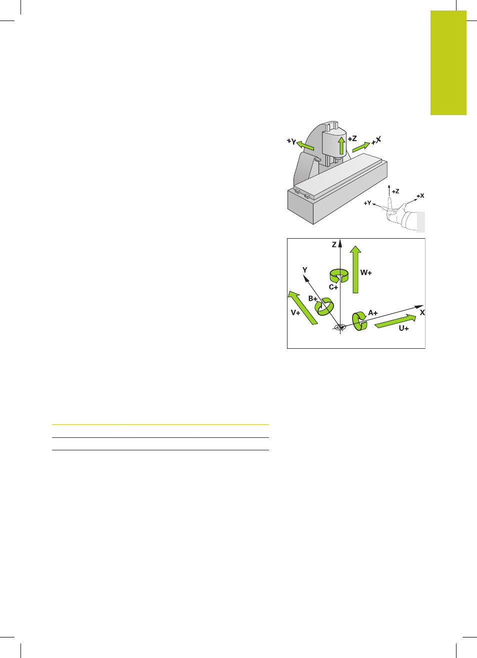
Reference system on milling machines
When using a milling machine, you orient tool movements to the
Cartesian coordinate system. The illustration at right shows how
the Cartesian coordinate system describes the machine axes. The
figure illustrates the right-hand rule for remembering the three
axis directions: the middle finger points in the positive direction of
the tool axis from the workpiece toward the tool (the Z axis), the
thumb points in the positive X direction, and the index finger in the
positive Y direction.
The TNC 620 can control up to 5 axes. The axes U, V and W
are secondary linear axes parallel to the main axes X, Y and Z,
respectively. Rotary axes are designated as A, B and C. The
illustration at lower right shows the assignment of secondary axes
and rotary axes to the main axes.
Designation of the axes on milling machines
The X, Y and Z axes on your milling machine are also referred to as
tool axis, principal axis (1st axis) and secondary axis (2nd axis). The
assignment of the tool axis is decisive for the assignment of the
principal and secondary axes.
Tool axis
Principal axis
Secondary axis
X
Y
Z
Y
Z
X
Z
X
Y