Miscellaneous functions for rotary axes 12.4 – HEIDENHAIN TNC 620 (81760x-02) ISO programming User Manual
Page 417
Miscellaneous functions for rotary axes 12.4
12
TNC 620 | User's ManualDIN/ISO Programming | 2/2015
417
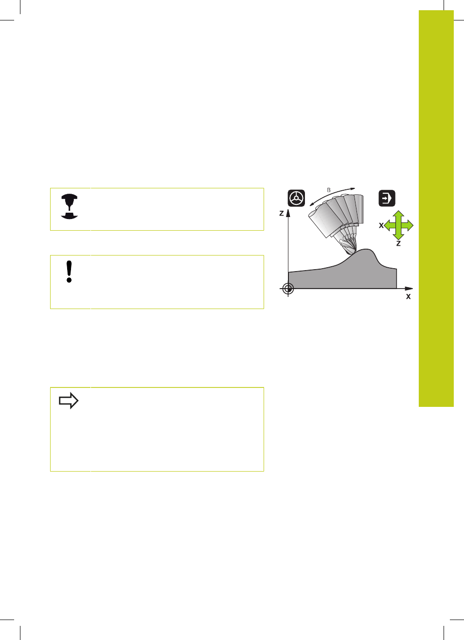
Maintaining the position of the tool tip when
positioning with tilted axes (TCPM): M128 (option 9)
Standard behavior
The TNC moves the tool to the positions given in the machining
program. If the position of a tilted axis changes in the program, the
resulting offset in the linear axes must be calculated, and traversed
in a positioning block.
Behavior with M128 (TCPM: Tool Center Point Management)
The machine geometry must be specified by the
machine tool builder in the description of kinematics.
If the position of a controlled tilted axis changes in the program, the
position of the tool tip to the workpiece remains the same.
Caution: Danger to the workpiece!
For tilted axes with Hirth coupling: Do not change
the position of the tilted axis until after retracting the
tool. Otherwise you might damage the contour when
disengaging from the coupling.
After
M128 you can program another feed rate, at which the TNC
will carry out the compensation movements in the linear axes.
If you wish to use the handwheel to change the position of the
tilted axis during program run, use
M128 in conjunction with M118.
Superimposing handwheel positioning is implemented with active
M128, depending on the setting in the 3D-ROT menu of the Manual
Operation mode of operation, in the active coordinate system or in
the machine-based coordinate system.
Before positioning with
M91 or M92 and before a T
BLOCK, RESET M128.
To avoid contour gouging you must use only
spherical cutters with
M128.
The tool length must refer to the spherical center of
the tool tip.
If
M128 is active, the TNC shows the TCPM symbol
in the status display.