Example: convex sphere machined with end mill – HEIDENHAIN TNC 620 (81760x-02) ISO programming User Manual
Page 346
Programming: Q parameters
9.12 Programming examples
9
346
TNC 620 | User's ManualDIN/ISO Programming | 2/2015
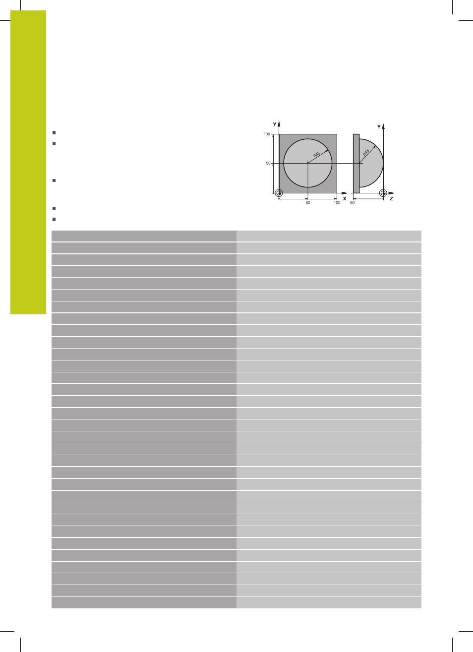
Example: Convex sphere machined with end mill
Program sequence
This program requires an end mill.
The contour of the sphere is approximated by many
short lines (in the Z/X plane, defined in Q14). The
smaller you define the angle increment, the smoother
the curve becomes.
You can determine the number of contour cuts
through the angle increment in the plane (defined in
Q18).
The tool moves upward in three-dimensional cuts.
The tool radius is compensated automatically
%SPHERE G71 *
N10 D00 Q1 P01 +50 *
Center in X axis
N20 D00 Q2 P01 +50 *
Center in Y axis
N30 D00 Q4 P01 +90 *
Starting angle in space (Z/X plane)
N40 D00 Q5 P01 +0 *
End angle in space (Z/X plane)
N50 D00 Q14 P01 +5 *
Angle increment in space
N60 D00 Q6 P01 +45 *
Sphere radius
N70 D00 Q8 P01 +0 *
Starting angle of rotational position in the X/Y plane
N80 D00 Q9 P01 +360 *
End angle of rotational position in the X/Y plane
N90 D00 Q18 P01 +10 *
Angle increment in the X/Y plane for roughing
N100 D00 Q10 P01 +5 *
Allowance in sphere radius for roughing
N110 D00 Q11 P01 +2 *
Set-up clearance for pre-positioning in the spindle axis
N120 D00 Q12 P01 +350 *
Feed rate for milling
N130 G30 G17 X+0 Y+0 Z-50 *
Definition of workpiece blank
N140 G31 G90 X+100 Y+100 Z+0 *
N150 T1 G17 S4000 *
Tool call
N160 G00 G40 G90 Z+250 *
Retract the tool
N170 L10.0 *
Call machining operation
N180 D00 Q10 P01 +0 *
Reset allowance
N190 D00 Q18 P01 +5 *
Angle increment in the X/Y plane for finishing
N200 L10.0 *
Call machining operation
N210 G00 G40 Z+250 M2 *
Retract the tool, end program
N220 G98 L10 *
Subprogram 10: Machining operation
N230 D01 Q23 P01 +Q11 P02 +Q6 *
Calculate Z coordinate for pre-positioning
N240 D00 Q24 P01 +Q4 *
Copy starting angle in space (Z/X plane)
N250 D01 Q26 P01 +Q6 P02 +Q108 *
Compensate sphere radius for pre-positioning
N260 D00 Q28 P01 +Q8 *
Copy rotational position in the plane
N270 D01 Q16 P01 +Q6 P02 -Q10 *
Account for allowance in the sphere radius
N280 G54 X+Q1 Y+Q2 Z-Q16 *
Shift datum to center of sphere
N290 G73 G90 H+Q8 *
Account for starting angle of rotational position in the plane
N300 G98 L1 *
Pre-position in the spindle axis
N310 I+0 J+0 *
Set pole in the X/Y plane for pre-positioning