Zero point for polar coordinates: pole i, j, Path contours – polar coordinates 6.5 – HEIDENHAIN TNC 620 (81760x-02) ISO programming User Manual
Page 229
Path contours – Polar coordinates
6.5
6
TNC 620 | User's ManualDIN/ISO Programming | 2/2015
229
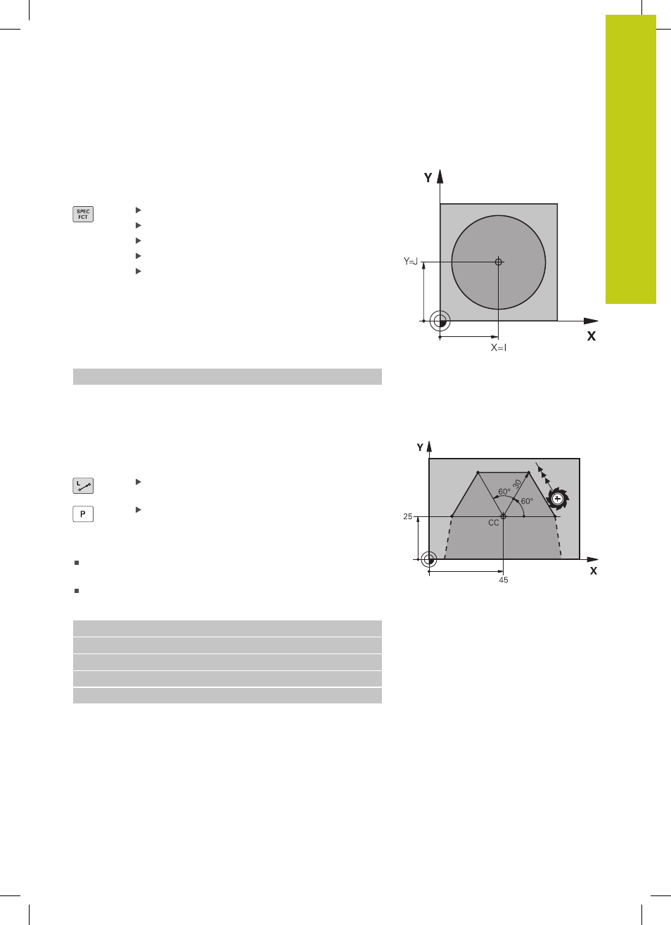
Zero point for polar coordinates: pole I, J
You can set the pole (I, J) at any point in the machining program,
before indicating points in polar coordinates. Set the pole in the
same way as you would program the circle center.
To program a pole, press the SPEC FCT key.
Press the PROGRAM FUNCTIONS soft key
Press the DIN/ISO soft key
Press the I or J soft key
Coordinates: Enter Cartesian coordinates for the
pole or, if you want to use the last programmed
position, enter
G29. Before programming polar
coordinates, define the pole. You can only define
the pole in Cartesian coordinates. The pole
remains in effect until you define a new pole.
Example NC blocks
N120 I+45 J+45 *
Straight line in rapid traverse G10 or straight line
with feed rate F G11
The tool moves in a straight line from its current position to the
straight-line end point. The starting point is the end point of the
preceding block.
Polar coordinate radius R: Enter the distance
from the pole CC to the straight-line end point.
Polar coordinate angle H: Angular position of the
straight-line end point between –360° and +360°
The sign of
H depends on the angle reference axis:
If the angle from the angle reference axis to
R is
counterclockwise:
H>0
If the angle from the angle reference axis to
R is clockwise: H<0
Example NC blocks
N120 I+45 J+45 *
N130 G11 G42 R+30 H+0 F300 M3 *
N140 H+60 *
N150 G91 H+60 *
N160 G90 H+180 *