Program layout – HEIDENHAIN TNC 620 (81760x-02) ISO programming User Manual
Page 52
First steps with the TNC 620
1.3
Programming the first part
1
52
TNC 620 | User's ManualDIN/ISO Programming | 2/2015
Program layout
NC programs should be arranged consistently in a similar manner.
This makes it easier to find your place, accelerates programming
and reduces errors.
Recommended program layout for simple, conventional
contour machining
1 Call tool, define tool axis
2 Retract the tool
3 Pre-position the tool in the working plane near the contour starting
point
4 In the tool axis, position the tool above the workpiece, or
preposition immediately to workpiece depth. If required, switch on
the spindle/coolant
5 Contour approach
6 Contour machining
7 Contour departure
8 Retract the tool, end program
Further information on this topic
Contour programming: see "Programming tool movements for
workpiece machining", page 202
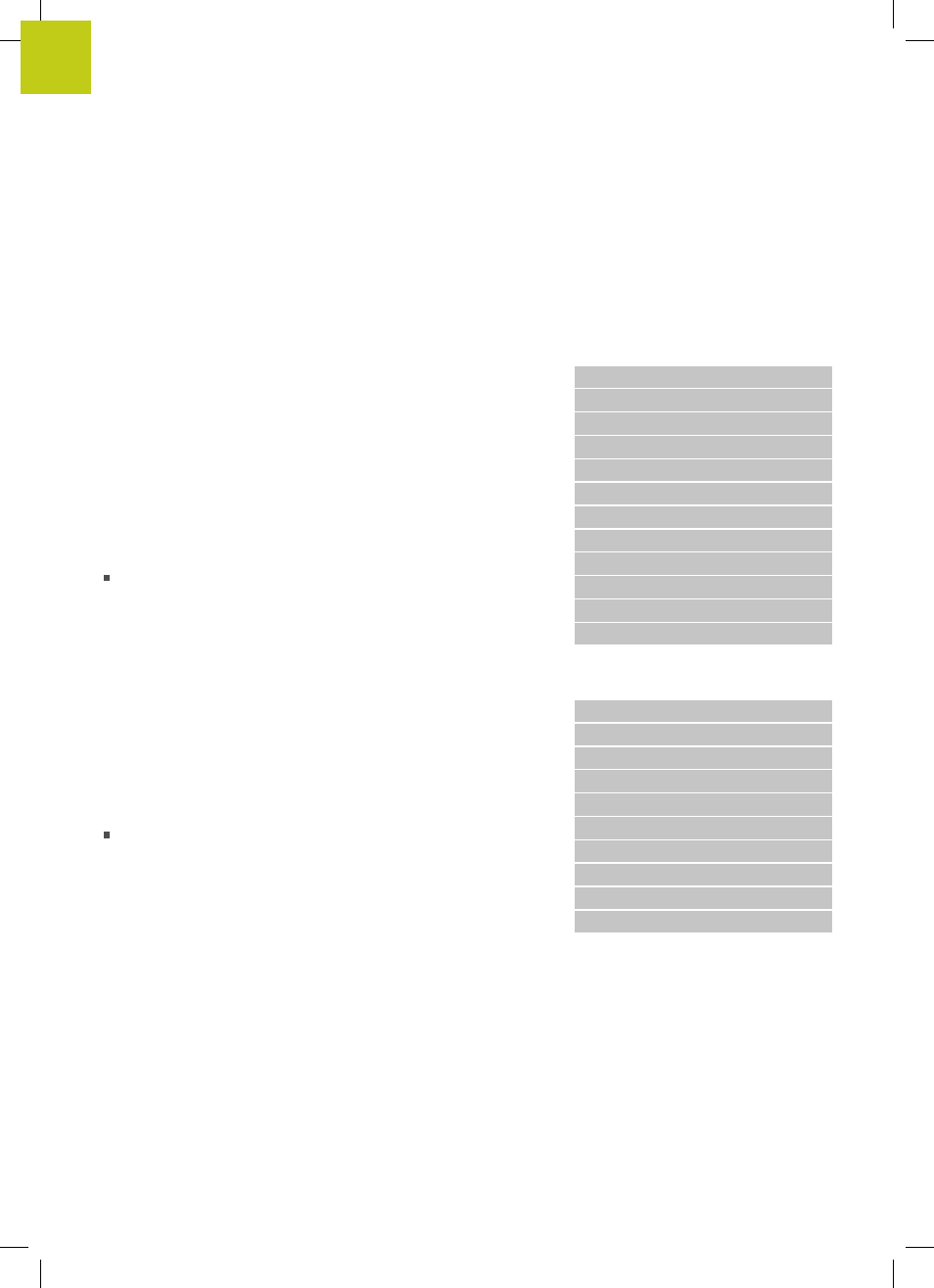
Layout of contour machining
programs
%BSPCONT G71 *
N10 G30 G71 X... Y... Z... *
N20 G31 X... Y... Z... *
N30 T5 G17 S5000 *
N40 G00 G40 G90 Z+250 *
N50 X... Y... *
N60 G01 Z+10 F3000 M13 *
N70 X... Y... RL F500 *
...
N160 G40 ... X... Y... F3000 M9 *
N170 G00 Z+250 M2 *
N99999999 BSPCONT G71 *
Recommended program layout for simple cycle programs
1 Call tool, define tool axis
2 Retract the tool
3 Define the fixed cycle
4 Move to the machining position
5 Call the cycle, switch on the spindle/coolant
6 Retract the tool, end program
Further information on this topic
Cycle programming: See User’s Manual for Cycles
Cycle program layout
%BSBCYC G71 *
N10 G30 G71 X... Y... Z... *
N20 G31 X... Y... Z... *
N30 T5 G17 S5000 *
N40 G00 G40 G90 Z+250 *
N50 G200... *
N60 X... Y... *
N70 G79 M13 *
N80 G00 Z+250 M2 *
N99999999 BSBCYC G71 *