Circular interpolation (mcw, mcc) -11 – Yaskawa MotionSuite Series Machine Controller Programming Manual User Manual
Page 52
MotionSuite™ Series Machine Controller Programming Manual
Chapter 2: Motion Commands
2-11
2.1.3
Circular Interpolation (MCW, MCC)
!
!
!
! Outline
The circular interpolation (MCW, MCC) command simultaneously moves 2 axes on the
designated plane, from the current position to the end position, along a circular arc
determined by the central position (U-V) or the radius value (R), by the interpolation feed
speed.
!
!
!
! Detailed Explanation
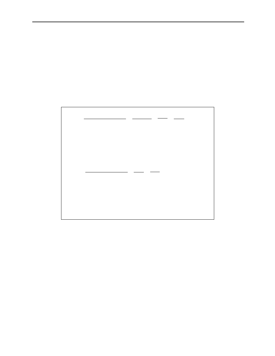
An example of the designating method is shown as follows:
The rotational direction of the circular interpolation command is shown as follows:
MCW: Clockwise (CW)
MCC: Counterclockwise (CCW)
Important Points
• Before executing the circular interpolation command, designate the plane of the circular
interpolation by the coordinate plane designation (PLN) command. For the circular
interpolation command, the rotational direction (MCW or MCC) of the circular arc must
be designated. Designate the end position and circular arc center of the horizontal axis
and the vertical axis on the designated plane using axis1 and axis2.
• Designate the end position and circular arc center in the order corresponding with the
horizontal axis and vertical axis names which are designated by the PLN command.
MCW [axis1]—[axis2]—
A
U—V—
B
T—
C
F—;
D
A: End position
B: Central position
C: Turn number
D: Interpolation feed speed
A: End
B: Radius
C: Interpolation feed speed
Note: When the central position is designated, multiple circular
arcs can be designated. (Omission is also possible.)
Or,
MCC
[axis1]—[axis2]—
A
R—
B
F—;
C