Yaskawa MotionSuite Series Machine Controller Programming Manual User Manual
Page 95
MotionSuite™ Series Machine Controller Programming Manual
Chapter 3: Advanced Programming Methods
3-10
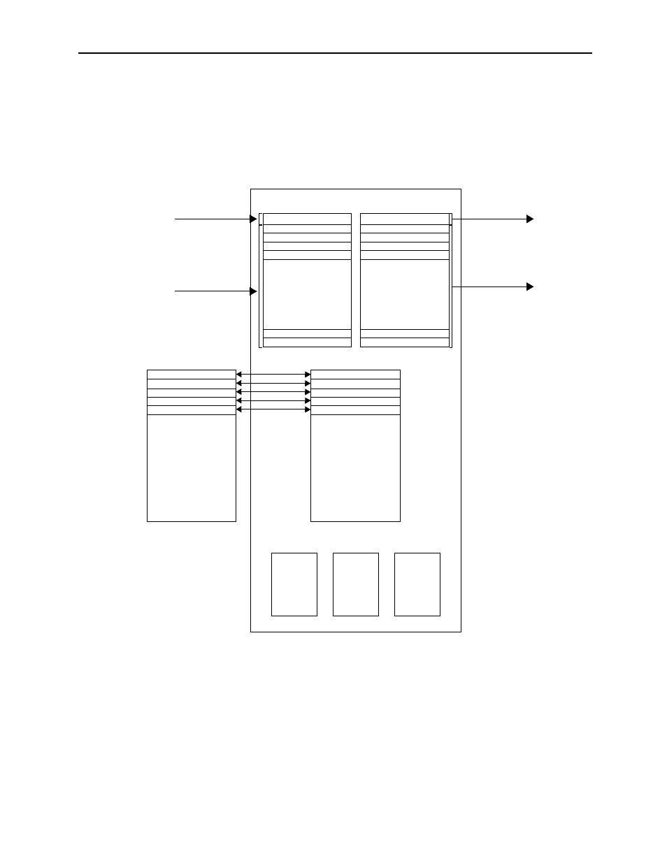
! Relationship Between the I/O Register and Function Register
The following illustration shows the interaction between the I/O register designated by the
UFC command and the function register.
Supplement
The S, M, I, O, and C registers are used in the same way as the DWG registers.
Input
Function Register
Output
X Register
(Input Register)
Y Register
(Output Register)
YB000000~YB00000F
YW0001
YW0002
YW0003
YW0004
•
•
•
•
•
•
•
•
YW00014
YW00016
A Register
XW00014
XW00016
XW00014
XW00016
XW00014
XB000000~XB00000F
XW0001
XW0002
XW0003
XW0004
•
•
•
•
•
•
•
•
XW00014
XW00016
Address Input
MW00100
MW00101
MW00102
MW00103
MW00104
Bit-type data output
B-VAL
I-REG
L-REG Output
Bit-type data input
B-VAL
I-REG
L-REG input
(Up to 16 bits)
(Up to 16 words)
MA00100
Z Register
# Register
D Register
Figure 3.7: I/O Register and Function Register Relationship