Zero-point return signal connection – Yaskawa MotionSuite Series Machine Controller Programming Manual User Manual
Page 68
MotionSuite™ Series Machine Controller Programming Manual
Chapter 2: Motion Commands
2-27
!
!
!
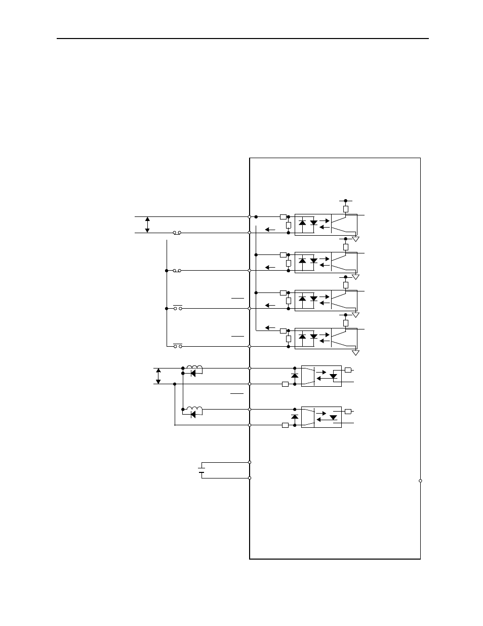
! Zero-point Return Signal Connection
The “Deceleration LS” and “Zero-point LS” used with the zero-point return are connected
to the 1CN of the servo amplifier.
• The “Deceleration LS”: 1CN, 9pin, Zero-point deceleration LS (/DEC)
• The “Zero-point LS”:
1CN, 10pin, External latch input (/EXT)
The connection is illustrated as follows:
Servo Amplifier
(SGD-###N Type) (SGDB-###N Type)
•[Decel LS]
→
(ON on LS side)
Zero-point return decel LS
•[Zero-point LS]
→
(ON on latch side)
External latch LS
(OT when OFF.)
Overtravel on reverse running
(OT when OFF.)
Overtravel on forward running
(OFF when ALARM.)
Alarm output
(OFF when brake input is OK.)
Brake interlock output
(3.3~4.5V)
Backup battery
→ Forward running
prohibited
→ Reverse running
prohibited
→ Zero-point return
decel LS ON
→ External latch
signal ON
← External latch
signal ON
← Brake interlock
3.3K
6
+24V
P-OT
7
Approx.7mA
P-LS
OV
N-OT
8
N-LS
DEC-LS
9
EXT-LS
DEC
EXT
10
ALM
ALM
+24V
3
ALM-SG
4
BK
ALM-SG
1
2
BAT
BATO
14
15
BRK
OV
26