V/f pattern setting examples, 5 basic operation – Yaskawa J1000 Compact V/f Control Drive User Manual
Page 102
n
V/f Pattern Setting Examples
This section provides examples of how to set a V/f pattern using E1-04 to E1-10.
Table 4.7 V/f Pattern Examples
Example
Specification
Characteristic
Application
A
50 Hz
Constant torque
For general purpose applications. Torque
remains constant regardless of changes to
speed.
B
60 Hz (default setting)
C
60 Hz (with 50 Hz base)
D
72 Hz (with 60 Hz base)
E
50 Hz, Heavy Duty 2
Derated torque
For fans, pumps, and other applications
that require torque derating relative to the
load.
F
50 Hz, Heavy Duty 1
G
50 Hz, Heavy Duty 1
H
50 Hz, Heavy Duty 2
I
50 Hz, mid starting torque
High starting torque
Select high starting torque when:
• Wiring between the drive an motor
exceeds 150 m
• A large amount of starting torque is
required
• An AC reactor is installed
J
50 Hz, high starting torque
K
60 Hz, mid starting torque
L
60 Hz, high starting torque
M
90 Hz (with 60 Hz base)
Constant output
When operating at greater than 60 Hz the
output voltage will be constant.
N
120 Hz (with 60 Hz base)
O
180 Hz (with 60 Hz base)
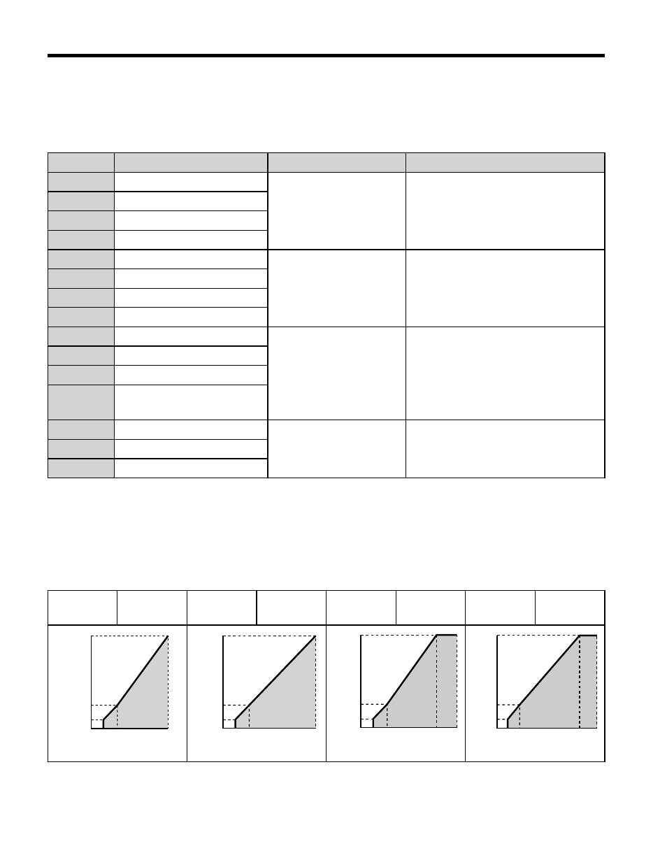
The following tables show details on V/f patterns.
The following graphs are for 200 V class drives. Double the values when using a 400 V class
drive.
V/f Pattern Examples
Table 4.8 Constant Torque Characteristics, Examples A to D
Example A
50 Hz
Example B
60 Hz
(default)
Example C
60 Hz
Example D
72 Hz
0
12
200
1.3 2.5
50
16
Voltage (V)
Frequency (Hz)
0
12
16
200
1.5 3
60
Voltage (V)
Frequency (Hz)
0
12
16
200
1.5 3
60
50
Voltage (V)
Frequency (Hz)
0
12
16
200
1.5 3
72
60
Voltage (V)
Frequency (Hz)
4.5 Basic Operation
102
YASKAWA ELECTRIC TOEP C710606 26D YASKAWA AC Drive – J1000 Quick Start Guide