2 standard connection diagram – Yaskawa J1000 Compact V/f Control Drive User Manual
Page 41
<7>
Monitor outputs work with devices such as analog frequency meters, ammeters,
voltmeters and wattmeters; they are not intended for use as a feedback-type of signal.
WARNING! Sudden Movement Hazard. Do not close the wiring for the control circuit unless the multifunction
input terminal parameter is properly set (S5 for 3-Wire; H1-05 = “0”). Improper sequencing of run/stop circuitry
could result in death or serious injury from moving equipment.
WARNING! Sudden Movement Hazard. Ensure start/stop and safety circuits are wired properly and in the
correct state before energizing the drive. Failure to comply could result in death or serious injury from moving
equipment. When programmed for 3-Wire control, a momentary closure on terminal S1 may cause the drive
to start.
WARNING! When 3-Wire sequence is used, set the drive to 3-Wire sequence before wiring the control
terminals and ensure parameter b1-17 is set to 0 (drive does not accept a run command at power up (default).
If the drive is wired for 3-Wire sequence but set up for 2-Wire sequence (default) and if parameter b1-17 is
set to 1 (drive accepts a Run command at power up), the motor will rotate in reverse direction at power up of
the drive and may cause injury.
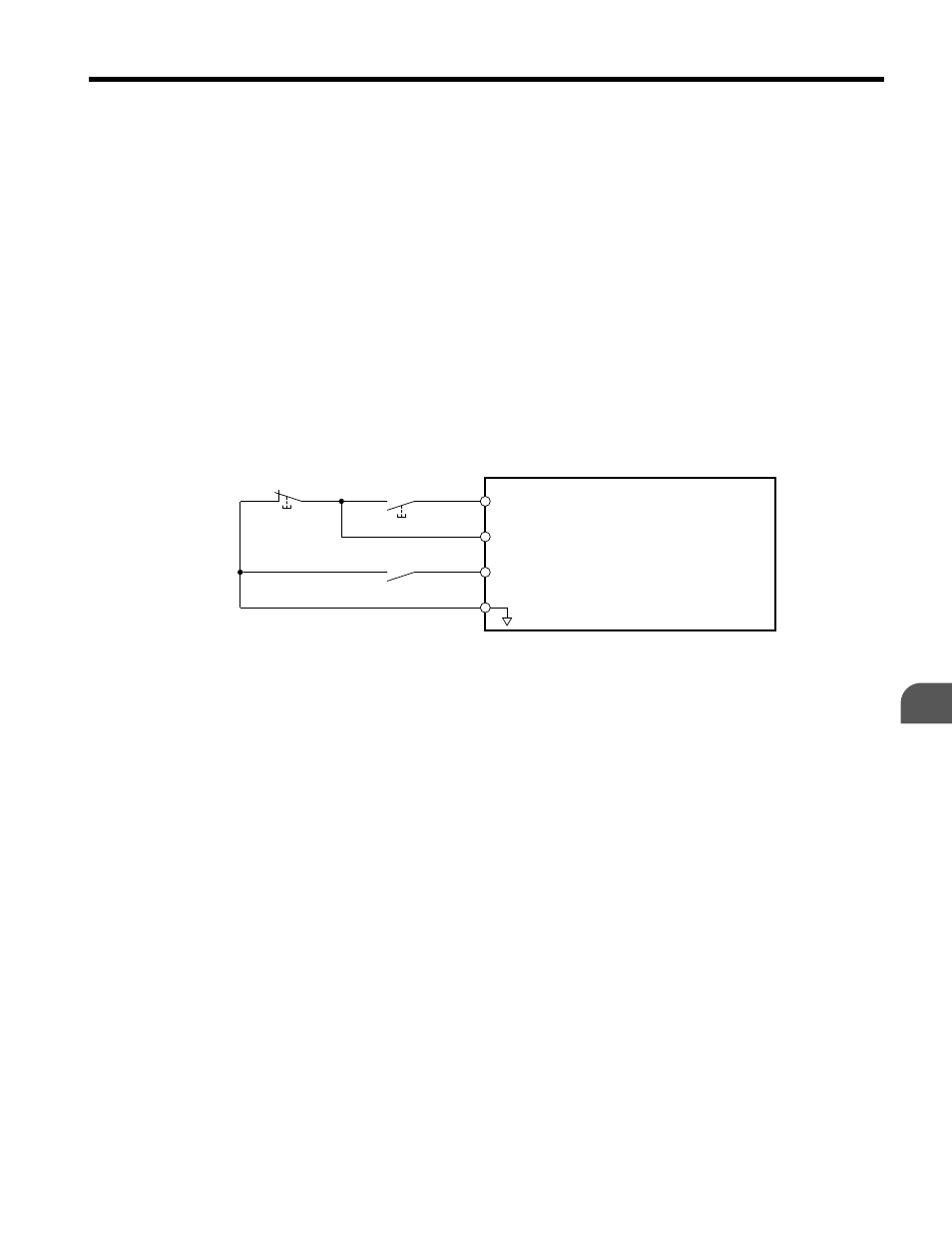
illustrates an example of a 3-Wire sequence.
Drive
Sequence input common
Run relay (N.O.)
Stop relay (N.C.)
Run command (run on momentary close)
Stop command (stop on momentary open)
Foward/reverse command
(multi-function input: H1-05 = 0)
S1
S2
S5
SC
Figure 3.2 3-Wire Sequence
3.2 Standard Connection Diagram
YASKAWA ELECTRIC TOEP C710606 26D YASKAWA AC Drive – J1000 Quick Start Guide
41
3
Electrical Installation