Using, Figure 3.13, Figure 3.14 – Yaskawa J1000 Compact V/f Control Drive User Manual
Page 57: 7 control circuit wiring
S1 S2
S3 S4
S5
SC A1 +V
AC AM AC
A
D
C
E
B
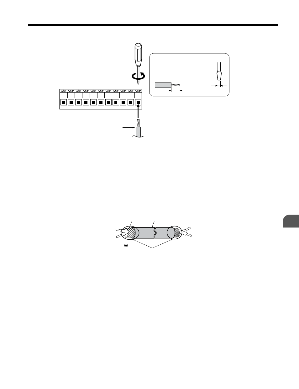
Preparing wire
terminal ends
A – Control terminal block
B – Avoid fraying wire
strands when stripping
insulation from wire.
Strip length 5.5 mm.
C – Single wire or stranded
wire
D – Loosen screw to insert
wire.
E – Blade depth of 0.4 mm or
less
Blade width of 2.5 mm or
less
Figure 3.13 Terminal Board Wiring Guide
A
F
C
D
E
B
A – Drive side
B – Connect shield to ground
terminal of drive.
C – Insulation
D – Control device side
E – Shield sheath (Insulate
with tape)
F – Shield
Figure 3.14 Preparing the Ends of Shielded Cables
When setting the frequency by analog reference from an external potentiometer, use shielded
twisted-pair wires and ground the shield of twisted-pair wires to the ground terminal of the
drive.
NOTICE: The analog signal lines between the drive and the operator station or peripheral equipment should
not exceed 50 meters when using an analog signal from a remote source to supply the frequency reference.
Failure to comply could result in poor system performance.
3.7 Control Circuit Wiring
YASKAWA ELECTRIC TOEP C710606 26D YASKAWA AC Drive – J1000 Quick Start Guide
57
3
Electrical Installation