B.2 parameter table – Yaskawa J1000 Compact V/f Control Drive User Manual
Page 219
No.
Name
Description
Range Def. Mode Addr.
Hex
Pg.
C6-02
Carrier
Frequency
Selection
Selects the carrier frequency
1 : 2.0 kHz
2 : 5.0 kHz
3 : 8.0 kHz
4 : 10.0 kHz
5 : 12.5 kHz
6 : 15.0 kHz
7 : Swing PWM
8 to E : No setting possible
F: User defined (determined by C6-03 through
C6-05)
1 to F
<2>
S
224
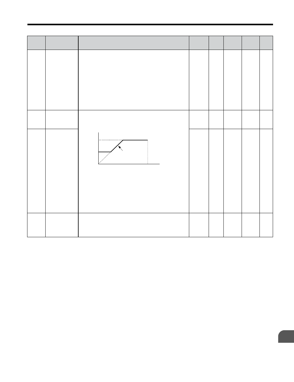
C6-03
Carrier
Frequency
Upper Limit
C6-03 and C6-04 set upper and lower limits for the
carrier frequency.
Note: Set C6-02 to F before setting C6-03.
carrier frequency
E1-04
max output
frequency
output frequency
× (C6-05) × K
output
frequency
C6-03
C6-04
The coefficient K depends on C6-03:
C6-03 ≥ 10.0 kHz: K = 3
10.0 kHz > C6-03 ≥ 5.0 kHz: K = 2
5.0 kHz > C6-03: K = 1
When C6-05 ≤ 6, C6-04 is disabled (makes the
carrier frequency C6-03 value).
1.0 to
15.0
<3>
O
225
–
C6-04
Carrier
Frequency
Lower Limit
1.0 to
15.0
<3>
O
226
–
C6-05
Carrier
Frequency
Proportional
Gain
Sets the relationship of output frequency to carrier
frequency when C6-02 = F.
00 to 99
<3>
O
227
–
<1>
Parameter can be changed during run.
<2>
Default setting value is dependent on parameter o2-04, Drive Model Selection and C6-01, Drive Duty Selection.
<3>
Default setting value is dependent on parameter C6-02, Carrier Frequency Selection.
B.2 Parameter Table
YASKAWA ELECTRIC TOEP C710606 26D YASKAWA AC Drive – J1000 Quick Start Guide
219
B
Parameter List