Digital output: h2-01, Analog outputs: h4-01 to h4-03 – Yaskawa J1000 Compact V/f Control Drive User Manual
Page 105
No.
Parameter Name
Setting Method
E2-03
Motor No-Load Current
Set motor no-load current at rated voltage and rated frequency.
Contact the motor manufacturer to get the no-load current. This information is
not usually written on the motor nameplate.
The default no-load current is for a Yaskawa 4-pole motor.
E2-05
Motor Line-to-Line
Resistance
Sets the phase-to-phase motor resistance in ohms.
u
Digital Output: H2-01
Parameter H2-01 assigns functions to digital output terminals MA, MB, and MC. Set this
parameter as required by the application. Default value is listed below.
NOTICE: Do not assign a function that repeats ON/OFF frequently to terminals MA and MB. Failure to comply
will reduce the relay contact lifetime. The expected number of relay contact switching times is normally
200,000 times (current 1 A, resistance load).
No.
Parameter Name
Default
H2-01
Terminal MA, MB and MC Function Selection (relay)
E: Fault
Note:
The setting range for H2-01 is 0 to 13D.
Refer to Parameter List on page 213
for more information.
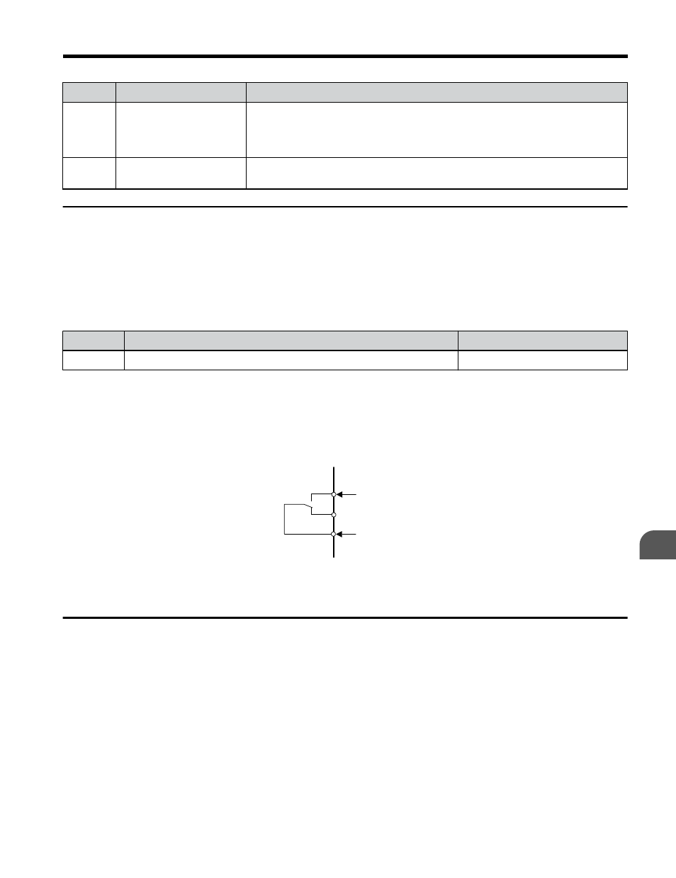
Multi-Function Contact Outputs
250 Vac, 10 mA - 1 A
30 Vdc, 10 mA - 1 A
(standard default setting)
MA
MB
MC
Fault
Fault
Figure 4.17 Digital Output Connection Diagram
u
Analog Outputs: H4-01 to H4-03
Group U parameters can be used to observe the drive status (operating conditions) through
the LED operator. Analog outputs corresponding to these monitors can be obtained on analog
output terminal AM when programmed with parameter group H4. Some Group U monitors
are not available as analog outputs.
4.5 Basic Operation
YASKAWA ELECTRIC TOEP C710606 26D YASKAWA AC Drive – J1000 Quick Start Guide
105
4
Start-Up Programming & Operation