28 (1) preparation – Yaskawa Sigma-5 User Manual: Design and Maintenance - Rotary Motors - MECHATROLINK-II Communications Reference User Manual
Page 181
5 Adjustments
5.4.1 Advanced Autotuning by Reference
5-28
(1) Preparation
Check the following settings before performing advanced autotuning by reference. The message “NO-OP”
indicating that the settings are not appropriate will be displayed, if all of the following conditions are not met.
• The SERVOPACK must be in Servo Ready status (Refer to 4.8.4).
• There must be no overtravel.
• The servomotor power must be OFF.
• The position control must be selected when the servomotor power is ON.
• The gain selection switch must be in manual switching mode (Pn139.0 = 0).
• Gain setting 1 must be selected.
• The test without a motor function must be disabled. (Pn00C.0 = 0).
• All warnings must be cleared.
• The write prohibited setting parameter (Fn010) must be set to Write permitted (P.0000).
• The tuning-less function must be disabled (Pn170.0 = 0).
(2) When Advanced Autotuning by Reference Cannot Be Performed Successfully
Advanced autotuning by reference cannot be performed successfully under the following conditions. If the
result of autotuning is not satisfactory, perform one-parameter tuning (Fn203). Refer to 5.5 One-parameter
Tuning (Fn203) for details.
• The travel distance in response to references from the host controller is smaller than the set positioning com-
pleted width (Pn522).
• The motor speed in response to references from the host controller is smaller than the set rotation detection
level (Pn502).
• The stopping time, i.e., the period while the positioning completed /COIN signal is OFF, is 10 ms or less.
• The rigidity of the machine is low and vibration occurs when positioning is performed.
• The position integration function is used.
• P control operation (proportional control) is performed.
• The mode switch is used.
• The positioning completed width (Pn522) is too small.
Change only the overshoot detection level (Pn561) to finely adjust the amount of overshooting without chang-
ing the positioning completed width (Pn522). Because Pn561 is set by default to 100%, the allowable amount
of overshooting is the same amount as that for the positioning completed width.
When Pn561 is set to 0%, the amount of overshooting can be adjusted without any overshooting in the posi-
tioning completed width. If the setting of Pn561 is changed, however, the positioning time may be extended.
• Advanced autotuning by reference starts adjustments based on the positioning com-
pleted width (Pn522). Set the electronic gear ratio (Pn20E/Pn210) and positioning
completed width (Pn522) to the actual value during operation.
• Unless the positioning completed signal (/COIN) is turned ON within approximately 3
seconds after positioning has been completed, "WAITING" will flash. Furthermore,
unless the positioning completed signal (/COIN) is turned ON within approximately 10
seconds, "Error" will flash for 2 seconds and tuning will be aborted.
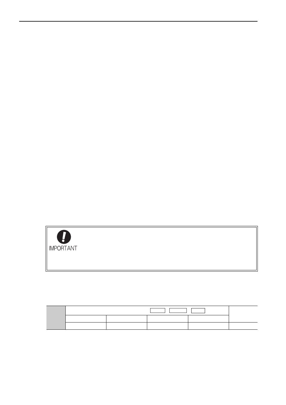
Pn561
Overshoot Detection Level
Classification
Setting Range
Setting Unit
Factory Setting
When Enabled
0 to 100
1%
100
Immediately
Setup
Speed
Position
Torque