7 connecting regenerative resistors, 1 connecting regenerative resistors, Warning – Yaskawa Sigma-5 User Manual: Design and Maintenance - Rotary Motors - MECHATROLINK-II Communications Reference User Manual
Page 79
3 Wiring and Connection
3.7.1 Connecting Regenerative Resistors
3-30
3.7 Connecting Regenerative Resistors
If the built-in regenerative resistor is insufficient, connect an external regenerative resistor by one of the fol-
lowing methods and set the regenerative resistor capacity (Pn600). As for precautions on selecting a regenera-
tive resistor and its specifications, refer to
Σ
-V Series Product Catalog (No.: KAEP S800000 42).
3.7.1 Connecting Regenerative Resistors
The following instructions show how to connect the regenerative resistors and SERVOPACKs.
(1) SERVOPACKs: Model SGDV-R70F, -R90F, -2R1F, -2R8F, -R70A, -R90A, -1R6A,
-2R8A
Connect an external regenerative resistor between the B1/ and B2 terminals on the SERVOPACK. After
connecting a resistor, select the capacity. For more information on how to set the capacity of regenerative
resistors, refer to 3.7.2 Setting Regenerative Resistor Capacity.
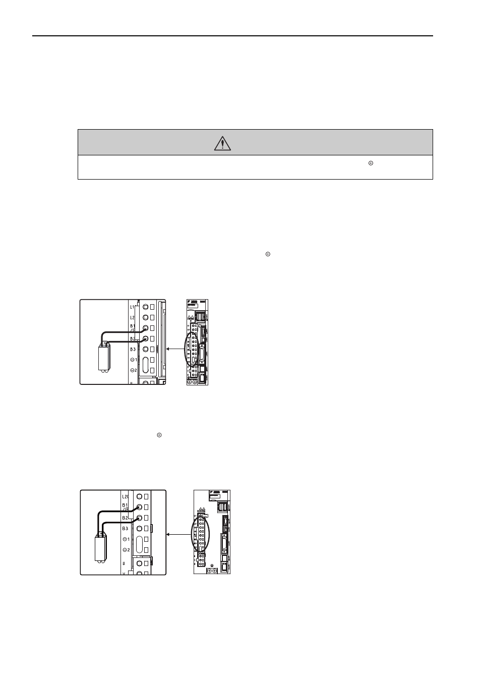
(2) SERVOPACKs: Model SGDV-3R8A, -5R5A, -7R6A, -120A, -180A, -200A, -330A,
-1R9D, -3R5D, -5R4D, -8R4D, -120D, -170D
Disconnect the wiring between the SERVOPACK’s B2 and B3 terminals and connect an external regenerative
resistor between the B1/ and B2 terminals. After connecting the resistor, select the capacity. For more infor-
mation on how to set the capacity of regenerative resistors, refer to 3.7.2 Setting Regenerative Resistor Capac-
ity.
Note: Be sure to take out the lead wire between the B2 and B3 terminals.
WARNING
• Be sure to connect the regenerative resistor correctly. Do not short-circuit between B1/ and B2.
Doing so may result in fire or damage to the regenerative resistor or SERVOPACK.
Enlarged View
M-II
Enlarged View
M-II