1 mechatrolink-ii communications settings, 1 setting switches sw1 and sw2, 1) settings for the sw2 dip switch – Yaskawa Sigma-5 User Manual: Design and Maintenance - Rotary Motors - MECHATROLINK-II Communications Reference User Manual
Page 88: M-ii
4.1 MECHATROLINK-II Communications Settings
4-3
4
Ope
rat
ion
4.1 MECHATROLINK-II Communications Settings
This section describes the switch settings necessary for MECHATROLINK-II communications.
4.1.1 Setting Switches SW1 and SW2
The SW2 DIP switch is used to make the settings for MECHATROLINK-II communications.
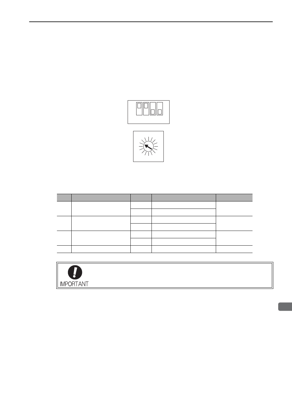
The station address is set using the rotary switch (SW1) and the DIP switch (SW2).
(1) Settings for the SW2 DIP Switch
The following table shows the settings of the DIP switch (SW2).
ON
OFF
SW2 (factory settings)
4
3
5
2
6
1
7
C
8
0
F
9
E
A
D
B
SW1 (factory setting)
1
2
3
4
M-II
SW2
Function
Setting
Description
Factory setting
Pin 1 Sets the baud rate.
OFF
4 Mbps (MECHATROLINK-I)
ON
ON
10 Mbps (MECHATROLINK-II)
Pin 2 Sets the number of trans-
mission bytes.
OFF
17 bytes
ON
ON
32 bytes
Pin 3 Sets the station address.
OFF
Station address = 40H + SW1
OFF
ON
Station address = 50H + SW1
Pin 4 Reserved. (Do not change.)
OFF
−
OFF
• When connecting to a MECHATROLINK-I network, turn OFF pins 1 and 2.
• When using a MECHATROLINK-I network (Baud rate: 4 Mbps), the settings for the num-
ber of transmission bytes is disabled and the number of transmission bytes is always 17.