1) wiring example, Rotation – Yaskawa Sigma-5 User Manual: Design and Maintenance - Rotary Motors - MECHATROLINK-II Communications Reference User Manual
Page 96
4.3 Basic Functions Settings
4-11
4
Ope
rat
ion
Note: The above operation delay time is an example when the power supply is turned ON and OFF on the DC side.
Be sure to evaluate the above times on the actual equipment before using the application.
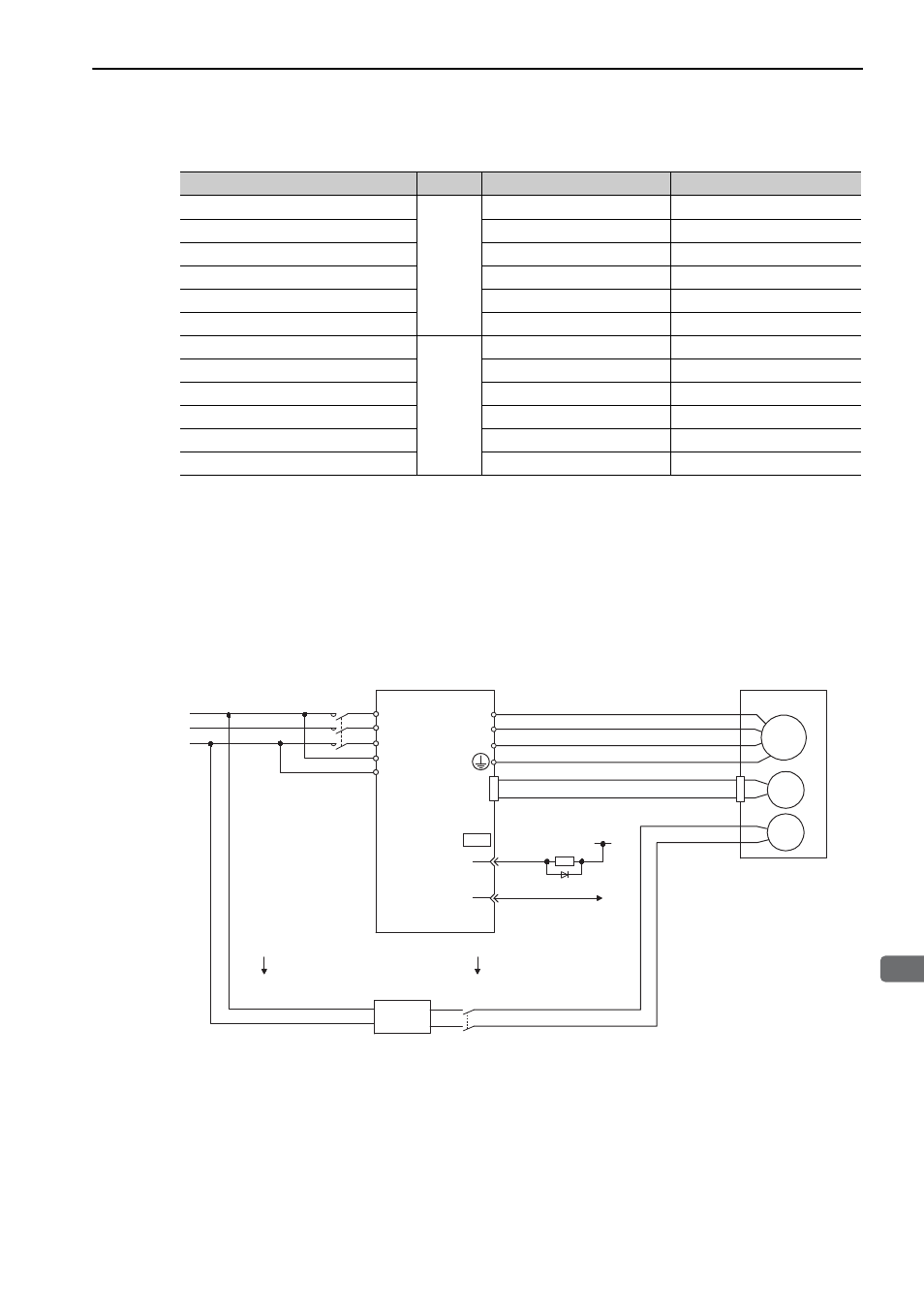
(1) Wiring Example
Use the brake signal (/BK) and the brake power supply to form a brake ON/OFF circuit. The following dia-
gram shows a standard wiring example.
The timing can be easily set using the brake signal (/BK).
Brake Operation Delay Time
Model
Voltage
Brake Release Time (ms)
Brake Applied Time (ms)
SGMJV-A5 to 04
24 VDC
60
100
SGMJV-08
80
100
SGMAV-A5 to 04
60
100
SGMAV-06 to 10
80
100
SGMPS-01, -08
20
100
SGMPS-02, -04, -15
40
100
SGMGV-03 to 20
24 VDC,
90 VDC
100
80
SGMGV-30, -44
170
100 (24 VDC), 80 (90 VDC)
SGMGV-55, -75, -1A
170
80
SGMGV-1E
250
80
SGMSV-10 to 25
170
80
SGMSV-30 to 50
100
80
M
BK
ENC
U
V
W
CN2
AC DC
BK-RY
BK-RY
+24 V
L1
L2
L3
L1C
L2C
(/BK+)
(/BK-)
CN1
1D
0 V
BK-R Y : Brake control relay
A 24 VDC power supply is not included.
Brake power supply for 90 V Input voltage 200-V models: LPSE-2H01-E
Input voltage 100-V models: LPDE-1H01-E
Servomotor
with holding
brake
SERVOPACK
Power supply
Red
Black
Blue or
yellow
White
Brake power
supply
DC side
AC side
Rotation