3 parameter recording table – Yaskawa Sigma-5 User Manual: Design and Maintenance - Rotary Motors - MECHATROLINK-II Communications Reference User Manual
Page 365
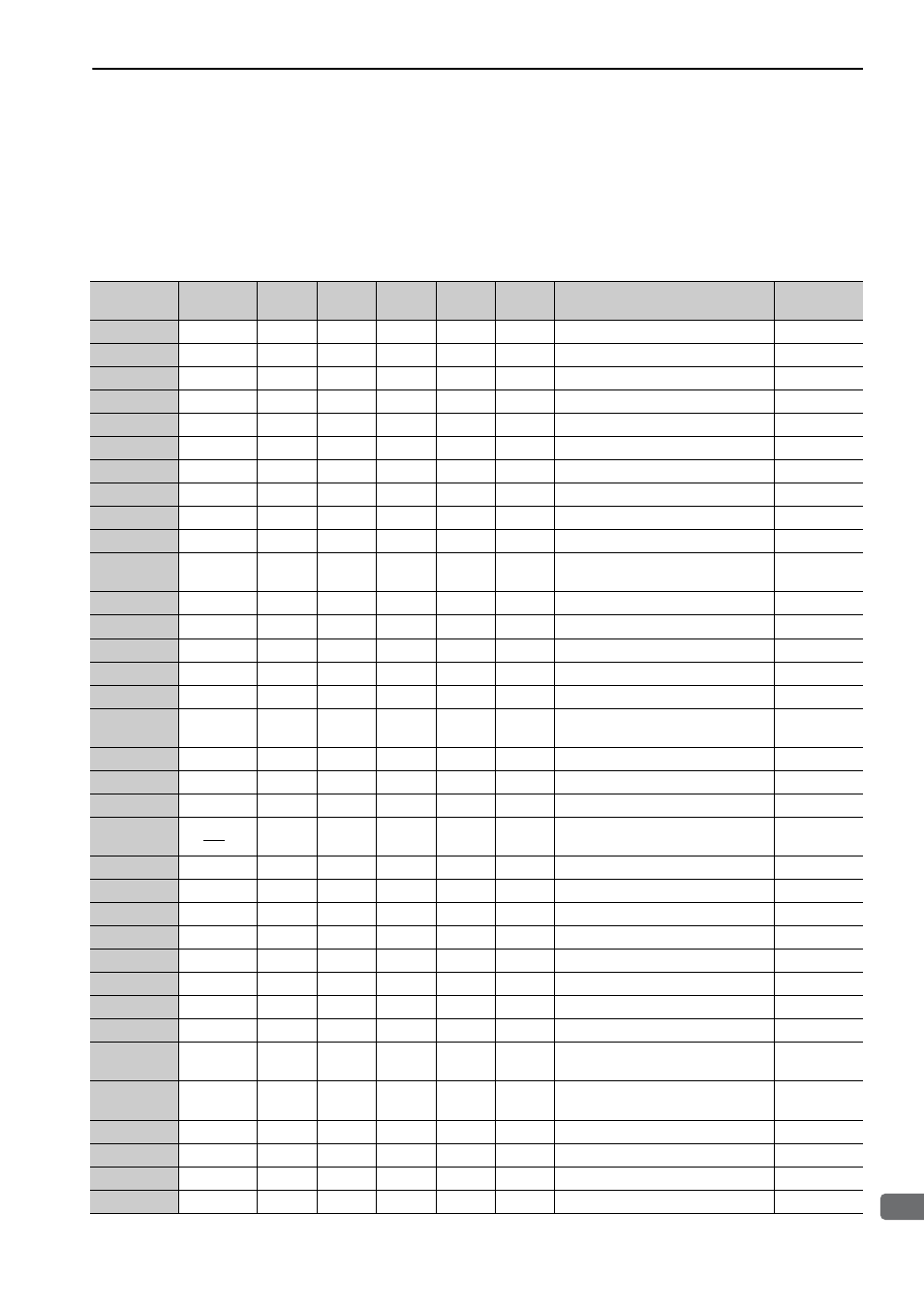
10.3 Parameter Recording Table
10-35
10
Ap
pend
ix
10.3 Parameter Recording Table
Use the following table for recording parameters.
Note: Pn10B, Pn170, and Pn408 have two kinds of digits: the digit which does not need the restart after changing the set-
tings and the digit which needs the restart. The underlined digits of the factory setting in the following table show
the digit which needs the restart.
Parameter
Factory
Setting
Name
When
Enabled
Pn000
0000
Basic Function Select Switch 0
After restart
Pn001
0000
Application Function Select Switch 1
After restart
Pn002
0000
Application Function Select Switch 2
After restart
Pn006
0002
Application Function Select Switch 6 Immediately
Pn007
0000
Application Function Select Switch 7 Immediately
Pn008
4000
Application Function Select Switch 8
After restart
Pn009
0010
Application Function Select Switch 9
After restart
Pn00B
0000
Application Function Select Switch B After restart
Pn00C
0000
Application Function Select Switch C After restart
Pn00D
0000
Application Function Select Switch D After restart
Pn081
0000
Application Function Select Switch
81
After restart
Pn100
400
Speed Loop Gain
Immediately
Pn101
2000
Speed Loop Integral Time Constant
Immediately
Pn102
400
Position Loop Gain
Immediately
Pn103
100
Moment of Inertia Ratio
Immediately
Pn104
400
2nd Speed Loop Gain
Immediately
Pn105
2000
2nd Speed Loop Integral Time Con-
stant
Immediately
Pn106
400
2nd Position Loop Gain
Immediately
Pn109
0
Feedforward Gain
Immediately
Pn10A
0
Feedforward Filter Time Constant
Immediately
Pn10B
0000
Application Function for Gain Select
Switch
−
Pn10C
200
Mode Switch (torque reference)
Immediately
Pn10D
0
Mode Switch (speed reference)
Immediately
Pn10E
0
Mode Switch (acceleration)
Immediately
Pn10F
0
Mode Switch (position error)
Immediately
Pn11F
0
Position Integral Time Constant
Immediately
Pn121
100
Friction Compensation Gain
Immediately
Pn122
100
2nd Gain for Friction Compensation
Immediately
Pn123
0
Friction Compensation Coefficient
Immediately
Pn124
0
Friction Compensation Frequency
Correction
Immediately
Pn125
100
Friction Compensation Gain Correc-
tion
Immediately
Pn131
0
Gain Switching Time 1
Immediately
Pn132
0
Gain Switching Time 2
Immediately
Pn135
0
Gain Switching Waiting Time 1
Immediately
Pn136
0
Gain Switching Waiting Time 2
Immediately