Yaskawa Sigma-5 User Manual: Design and Maintenance - Rotary Motors - MECHATROLINK-II Communications Reference User Manual
Page 338

10 Appendix
10.1.2 Parameters
10-8
Pn081
2
Application Function Select
Switch 81
0000 to 1111
−
0000
After restart
Setup
8.1.5
Pn100
2
Speed Loop Gain
10 to 20000
0.1 Hz
400
Immediately
Tuning
5.8.1
Pn101
2
Speed Loop Integral Time
Constant
15 to 51200
0.01 ms
2000
Immediately
Tuning
Pn102
2
Position Loop Gain
10 to 20000
0.1/s
400
Immediately
Tuning
Pn103
2
Moment of Inertia Ratio
0 to 20000
1%
100
Immediately
Tuning
Pn104
2
2nd Speed Loop Gain
10 to 20000
0.1 Hz
400
Immediately
Tuning
Pn105
2
2nd Speed Loop Integral Time
Constant
15 to 51200
0.01 ms
2000
Immediately
Tuning
Pn106
2
2nd Position Loop Gain
10 to 20000
0.1/s
400
Immediately
Tuning
Pn109
2
Feedforward Gain
0 to 100
1%
0
Immediately
Tuning
5.9.1
Pn10A
2
Feedforward Filter Time
Constant
0 to 6400
0.01 ms
0
Immediately
Tuning
Pn10B
2
Application Function for Gain
Select Switch
0000 to 5334
−
0000
−
−
−
(cont’d)
Parameter
No.
Size
Name
Setting
Range
Units
Factory
Setting
When
Enabled
Classification
Reference
Section
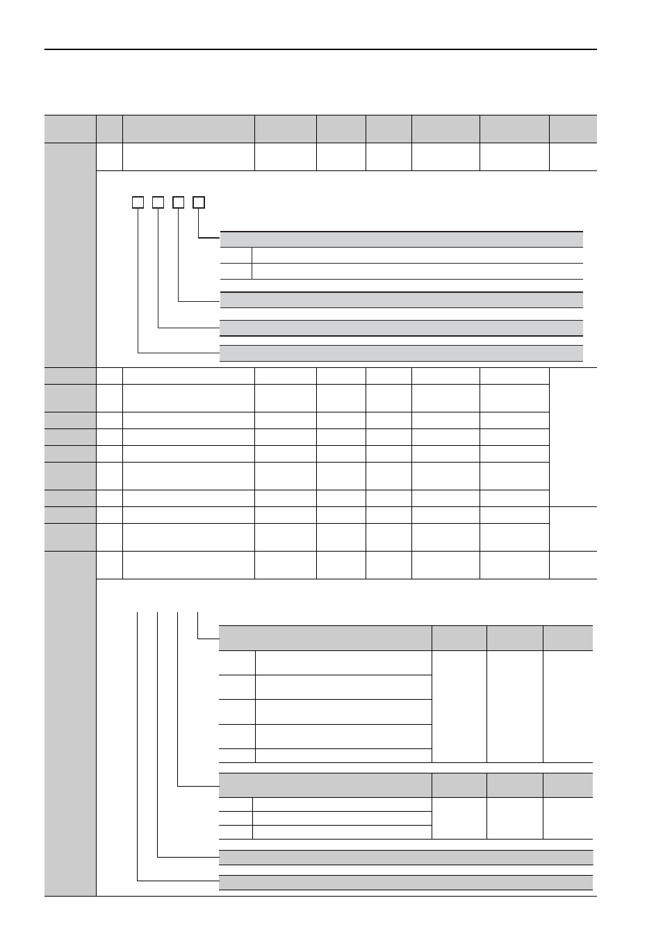
Reserved (Do not change.)
n.
Reserved (Do not change.)
0
1
Phase-C Pulse Output Selection
Outputs phase-C pulse only in forward direction.
Outputs phase-C pulse in forward and reverse direction.
Reserved (Do not change.)
4th
digit
3rd
digit
2nd
digit
1st
digit
Mode Switch Selection
When
Enabled
Classification
Reference
Section
0
Uses internal torque reference as the condition
(Level setting: Pn10C).
Immediately
Setup
5.9.2
1
Uses speed reference as the condition (Level
setting: Pn10D).
2
Uses acceleration as the condition (Level setting:
Pn10E).
3
Uses position error as the condition (Level setting:
Pn10F).
4
No mode switch function available.
Speed Loop Control Method
When
Enabled
Classification
Reference
Section
0
PI control
After restart
Setup
−
1
I-P control
2 to 3
Reserved (Do not change.)
Reserved (Do not change.)
Reserved (Do not change.)
4th 3rd 2nd 1st
digit digit digit digit
n.