11 three-phase 200 v sgdv-590a11a, -780a11a models, M-ii – Yaskawa Sigma-5 User Manual: Design and Maintenance - Rotary Motors - MECHATROLINK-II Communications Reference User Manual
Page 34
1 Outline
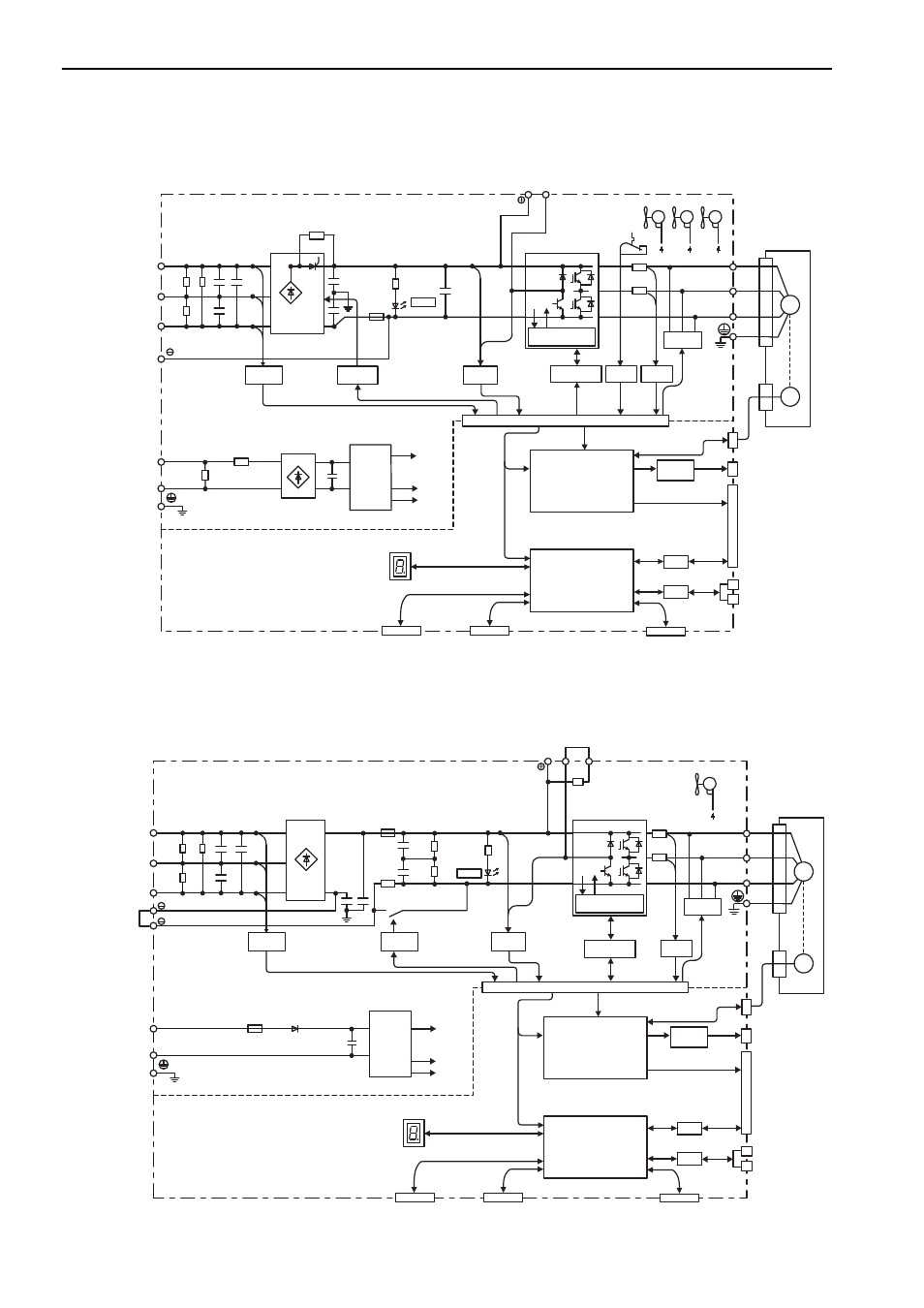
1.4.11 Three-phase 200 V SGDV-590A11A, -780A11A Models
1-14
1.4.11 Three-phase 200 V SGDV-590A11A, -780A11A Models
1.4.12 Three-phase 400 V, SGDV-1R9D11A, -3R5D11A, -5R4D11A Models
L1
B1/ B2
L2
L3
L1C
L2C
U
V
W
ENC
M
CHARGE
Main circuit
power supply
Control power
supply
+15 V
× 4
+5 V
±
12 V ±12 V
±
12 V
Current
sensor
Dynamic
brake circuit
Servomotor
Gate
drive
Voltage
sensor
Voltage
sensor
Varistor
Varistor
Temperature
sensor
Fan 1
Fan 2 Fan 3
Control
power
supply
Overheat protector,
overcurrent protector
Thyristor
drive
±
12 V
+
–
+
–
CN3
CN7
CN8
CN2
I/O
I/F
CN1
CN6A
CN6B
CN5
MECHATROLINK-
II
communications
CPU
(Position/speed
calculation, etc.)
Panel display
Digital operator
Personal
computer
Signal for safety fuction
Encoder output
pulse
Analog monitor
output
ASIC
(PWM control, etc.)
Analog
voltage
converter
I/O signal
46
L1
B1/ B2 B3
L2
L3
1
2
+24 V
0 V
U
V
W
ENC
M
CHARGE
+
–
+15 V
× 4
±12 V
+
–
+
–
+5 V
Current
sensor
Dynamic
brake circuit
Servomotor
Gate
drive
Voltage
sensor
Voltage
sensor
Varistor
Relay
drive
Fan
Control
power
supply
Overheat protector,
overcurrent protector
±
12 V
Main circuit
power supply
Control power
supply
(The 24 VDC
power supply is
not included.)
CN3
CN7
CN8
CN2
I/O
I/F
CN1
CN6A
CN6B
CN5
MECHATROLINK-
II
communications
CPU
(Position/speed
calculation, etc.)
Panel display
Digital operator
Personal
computer
Signal for safety fuction
Encoder output
pulse
Analog monitor
output
ASIC
(PWM control, etc.)
Analog
voltage
converter
I/O signal
M-II