5 wiring mechatrolink-ii communications, M-ii, Wi ring and c onne ctio n – Yaskawa Sigma-5 User Manual: Design and Maintenance - Rotary Motors - MECHATROLINK-II Communications Reference User Manual
Page 76
Advertising
3.5 Wiring MECHATROLINK-II Communications
3-27
3
Wi
ring and
C
onne
ctio
n
3.5 Wiring MECHATROLINK-II Communications
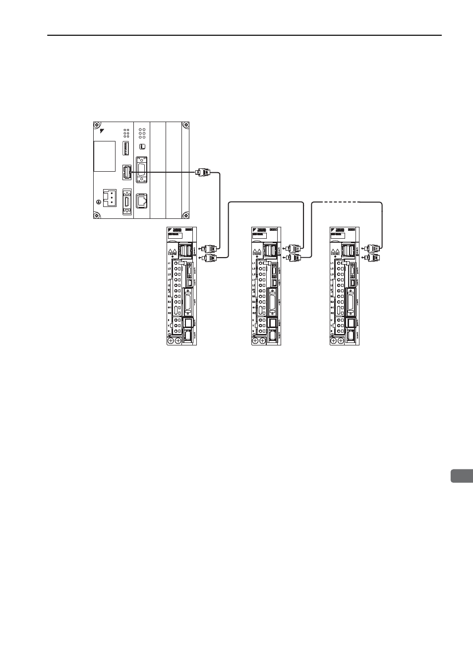
The following diagram shows an example of connections between a host controller and a SERVOPACK using
MECHATROLINK-II communications cables (CN6A, CN6B).
Note 1. The length of the cable between stations (L1, L2 ... Ln) must be 0.5 m or more.
2. The total cable length must be L1 + L2 ... + Ln
≤ 50.
3. When multiple SERVOPACKs are connected by MECHATROLINK-II communications cable, a terminator must
be installed at the final SERVOPACK.
Ln
L1
L2
Terminator
DC24V
DC 0V
MP2300
YASKAWA
TEST
ޓ
ޓ
ޓ
Option
Option
RDY
ALM
TX
RUN
ERR
BAT
MON
CNFG
INT
SUP
STOP
SW1
OFF
ON
BATTERY
CPU I/O
M-
I/II
218IF-01
ERR
COL
RX
RUN
STRX
TX
INIT
TEST
ON
OFF
PORT
10Base-T
M-II
Advertising