8 (4) power supply capacities and power losses – Yaskawa Sigma-5 User Manual: Design and Maintenance - Rotary Motors - MECHATROLINK-II Communications Reference User Manual
Page 57
3 Wiring and Connection
3.1.2 Using a Standard Power Supply (Single-phase 100 V, Three-phase 200 V, or Three-phase 400 V)
3-8
(4) Power Supply Capacities and Power Losses
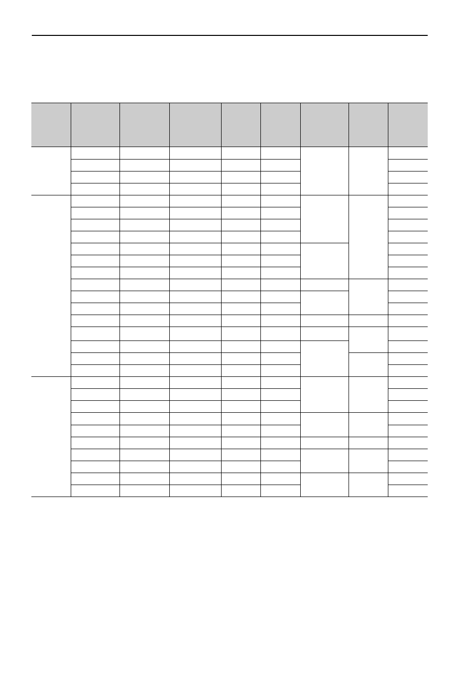
The following table shows the SERVOPACK’s power supply capacities and power losses.
∗1. The value in parentheses is for the JUSP-RA04-E regenerative resistor unit.
∗2. The value in parentheses is for the JUSP-RA05-E regenerative resistor unit.
∗3. The value in parentheses is for the JUSP-RA18-E regenerative resistor unit.
∗4. The value in parentheses is for the JUSP-RA19-E regenerative resistor unit.
Note 1. SGDV-R70F, -R90F, -2R1F, -2R8F, -R70A, -R90A, -1R6A, and -2R8A SERVOPACKs do not have built-in
regenerative resistors. Connect an external regenerative resistor if the regenerative energy exceeds the specified
value.
2. SGDV-470A, -550A, -590A, -780A, -210D, -260D, -280D, and -370D SERVOPACKs do not have built-in
regenerative resistors. Make sure that a regenerative resistor unit or an external regenerative resistor is connected.
Refer to 3.7 Connecting Regenerative Resistors for details.
3. Regenerative resistor power losses are the allowable losses. Take the following actions if this value is exceeded.
•Remove the lead or shorting bar between terminals B2 and B3 on the SERVOPACK main circuit for SGDV-
3R8A, -5R5A, -7R6A, -120A, -180A, -200A, -330A, and 400-V SERVOPACKs.
•Install an external regenerative resistor. Refer to 3.7 Connecting Regenerative Resistors for details.
4. Both the regenerative resistor unit and the external regenerative resistor are not included.
Main
Circuit
Power
Supply
Maximum
Applicable
Servomotor
Capacity
[kW]
SERVOPACK
Model
SGDV-
Power Supply
Capacity per
SERVOPACK
[kVA]
Output
Current
[Arms]
Main
Circuit
Power
Loss
[W]
Regenerative
Resistor
Power Loss
[W]
Control
Circuit
Power
Loss [W]
Total
Power
Loss [W]
Single-
phase,
100 V
0.05 R70F
0.2
0.66
5.4
–
17
22.4
0.1 R90F
0.3
0.91
7.8
24.8
0.2 2R1F
0.7
2.1
14.4
31.4
0.4 2R8F
1.4
2.8
25.6
42.6
Three-
phase,
200 V
0.05
R70A
0.2
0.66
5.1
–
17
22.1
0.1
R90A
0.3
0.91
7.3
24.3
0.2
1R6A
0.6
1.6
13.5
30.5
0.4
2R8A
1
2.8
24.0
41.0
0.5
3R8A
1.4
3.8
20.1
8
45.1
0.75
5R5A
1.6
5.5
43.8
68.8
1.0
7R6A
2.3
7.6
53.6
78.6
1.5
120A
3.2
11.6
65.8
10
22
97.8
2.0
180A
4
18.5
111.9
16
149.9
3.0
200A
5.9
19.6
113.8
161.4
5.0
330A
7.5
32.9
263.7
36
27
326.7
6.0
470A
10.7
46.9
279.4
(180)
*1
33
312.4
7.5
550A
14.6
54.7
357.8
(350)
*2
390.8
11
590A
21.7
58.6
431.7
48
479.7
15
780A
29.6
78
599.0
647.0
Three-
phase,
400 V
0.5
1R9D
1.1
1.9
24.6
14
21
59.6
1.0
3R5D
2.3
3.5
46.1
81.1
1.5
5R4D
3.5
5.4
71.3
106.3
2.0
8R4D
4.5
8.4
77.9
28
25
130.9
3.0
120D
7.1
11.9
108.7
161.7
5.0
170D
11.7
16.5
161.1
36
24
221.1
6.0
210D
12.4
20.8
172.7
(180)
*3
27
199.7
7.5
260D
14.4
25.7
218.6
245.6
11
280D
21.9
28.1
294.6
(350)
*4
30
324.6
15
370D
30.6
37.2
403.8
433.8