Yaskawa Sigma-5 User Manual: Design and Maintenance - Rotary Motors - MECHATROLINK-II Communications Reference User Manual
Page 71
Advertising
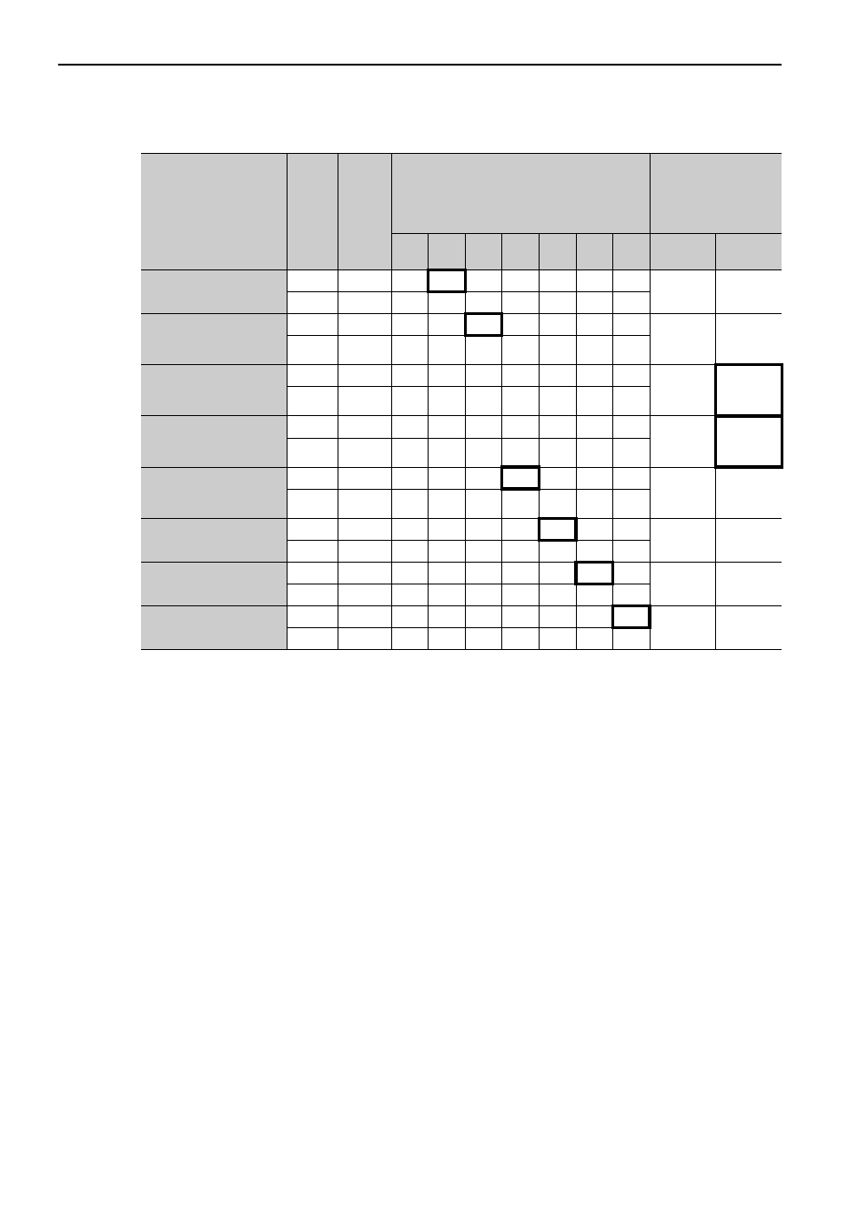
3 Wiring and Connection
3.3.1 Input Signal Allocations
3-22
∗ Always set to "Invalid."
Input Signal Names
and Parameters
Valid-
ity
Level
Input
Signal
CN1 Pin Numbers
Connection Not
Required
(SERVOPACK
judges the connec-
tion)
13
7
8
9
10
11
12
Always
ON
Always
OFF
Forward Run Prohibited
Pn50A.3
H
P-OT
0
1
2
3
4
5
6
7
8
L
/P-OT
9
A
B
C
D
E
F
Reverse Run Prohibit-
ed
Pn50B.0
H
N-OT
0
1
2
3
4
5
6
7
8
L
/N-OT
0
A
B
C
D
E
F
Forward External
Torque Limit
Pn50B.2
L
/P-CL
0
1
2
3
4
5
6
7
8
H
P-CL
9
A
B
C
D
E
F
Reserve External
Torque Limit
Pn50B.3
L
/N-CL
0
1
2
3
4
5
6
7
8
H
N-CL
9
A
B
C
D
E
F
Homing Deceleration
LS
Pn511.0
L
/DEC
0
1
2
3
4
5
6
7
8
H
DEC
9
A
B
C
D
E
F
External Latch Signal 1
Pn511.1
L
EXT1
*
*
*
*
4
5
6
7
8
H
/EXT1
*
*
*
*
D
E
F
External Latch Signal 2
Pn511.2
L
EXT2
*
*
*
*
4
5
6
7
8
H
/EXT2
*
*
*
*
D
E
F
External Latch Signal 3
Pn511.3
L
EXT3
*
*
*
*
4
5
6
7
8
H
/EXT3
*
*
*
*
D
E
F
Advertising