Altera Arria 10 Avalon-MM User Manual
Page 103
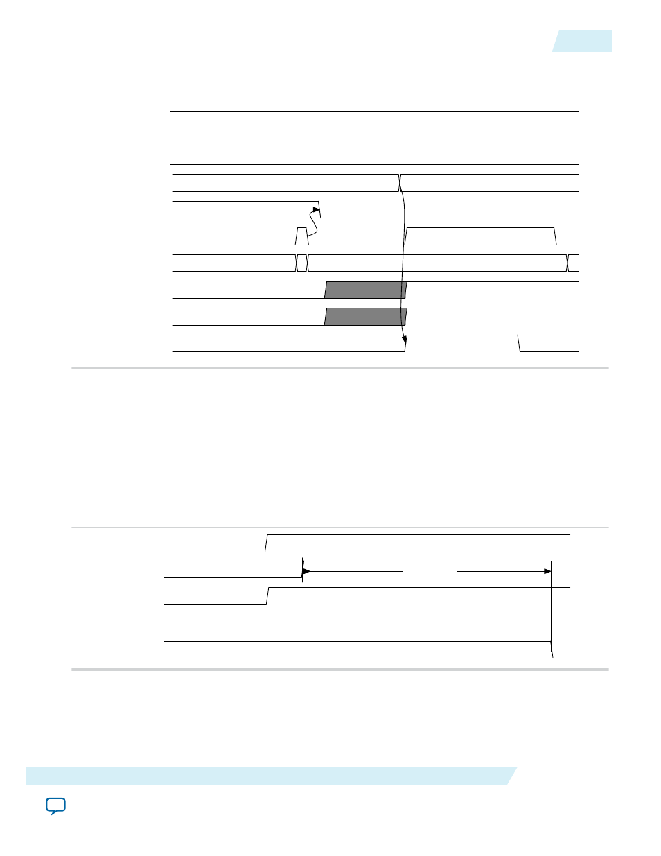
Figure 7-3: RX Transceiver Reset Sequence
busy_xcvr_reconfig
rx_pll_locked
rx_analogreset
ltssmstate[4:0]
txdetectrx_loopback
pipe_phystatus
pipe_rxstatus[2:0]
rx_signaldetect
rx_freqlocked
rx_digitalreset
3
0
01
The RX transceiver reset sequence includes the following steps:
1. After
rx_pll_locked
is asserted, the LTSSM state machine transitions from the Detect.Quiet to the
Detect.Active state.
2. When the
pipe_phystatus
pulse is asserted and
pipe_rxstatus[2:0]
= 3, the receiver detect
operation has completed.
3. The LTSSM state machine transitions from the Detect.Active state to the Polling.Active state.
4. The Hard IP for PCI Express asserts
rx_digitalreset
. The
rx_digitalreset
signal is deasserted
after
rx_signaldetect
is stable for a minimum of 3 ms.
Figure 7-4: TX Transceiver Reset Sequence
npor
pll_locked
npor_serdes
127 cycles
tx_digitalreset
The TX transceiver reset sequence includes the following steps:
1. After
npor
is deasserted, the IP core deasserts the
npor_serdes
input to the TX transceiver.
2. The SERDES reset controller waits for
pll_locked
to be stable for a minimum of 127
pld_clk
cycles
before deasserting
tx_digitalreset.
UG-01145_avmm
2015.05.14
Reset Sequence for Hard IP for PCI Express IP Core and Application Layer
7-3
Arria 10 Reset and Clocks
Altera Corporation