Altera Arria 10 Avalon-MM User Manual
Page 44
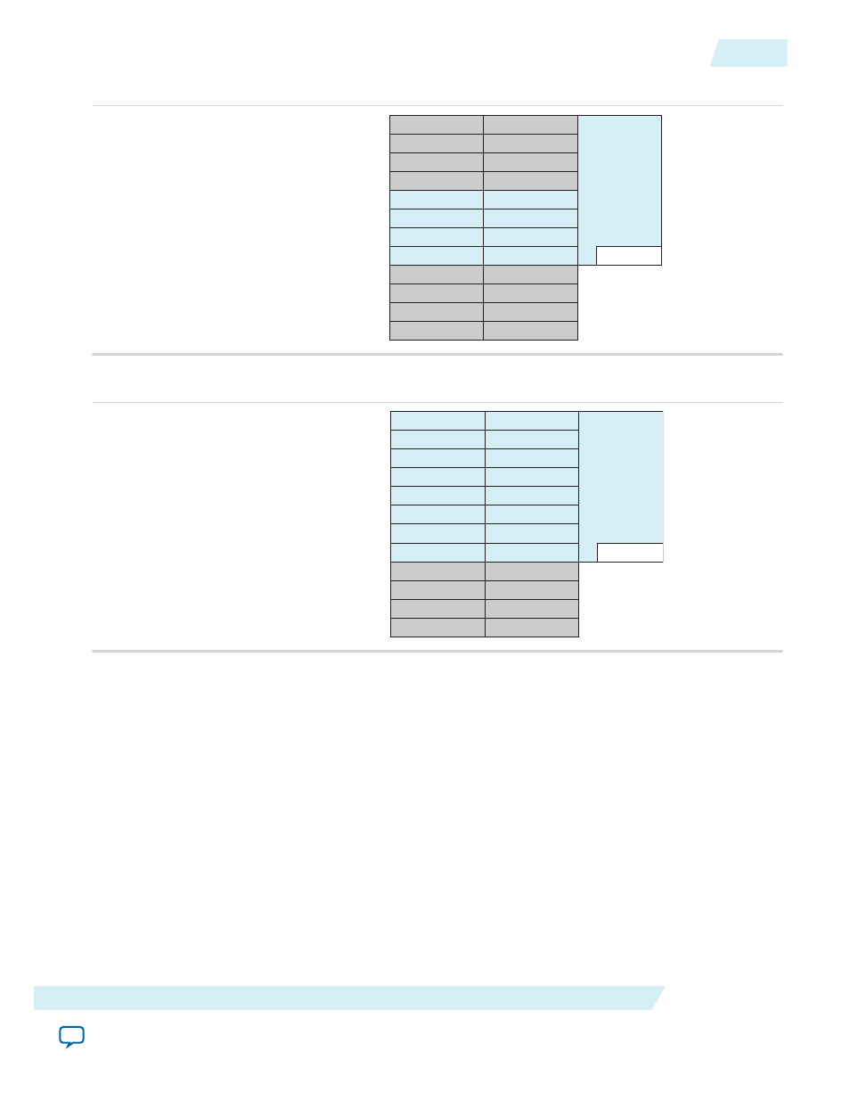
Figure 4-6: Arria 10 Gen1, Gen2, and Gen3 x4 Channel and Pin Placement
PMA Channel 5
PMA Channel 4
PMA Channel 3
PMA Channel 0
PMA Channel 3
PMA Channel 2
PMA Channel 1
PMA Channel 0
PCS Channel 5
PCS Channel 4
PCS Channel 3
PCS Channel 0
PCS Channel 3
PCS Channel 2
PCS Channel 1
PCS Channel 0
Hard IP Ch0
PMA Channel 1
PCS Channel 1
PMA Channel 4
PCS Channel 4
PMA Channel 5
PCS Channel 5
PMA Channel 2
PCS Channel 2
Hard IP
for PCIe
<txvr_block_N>_TX/RX_CH4N
<txvr_block_N>_TX/RX_CH5N
<txvr_block_N+1>_TX/RX_CH0N
<txvr_block_N+1>_TX/RX_CH1N
Figure 4-7: Arria 10 Gen1, Gen2, and Gen3 x8 Channel and Pin Placement
PMA Channel 5
PMA Channel 4
PMA Channel 3
PMA Channel 0
PMA Channel 3
PMA Channel 2
PMA Channel 1
PMA Channel 0
PCS Channel 5
PCS Channel 4
PCS Channel 3
PCS Channel 0
PCS Channel 3
PCS Channel 2
PCS Channel 1
PCS Channel 0
Hard IP
for PCIe
Hard IP Ch0
PMA Channel 1
PCS Channel 1
PMA Channel 4
PCS Channel 4
PMA Channel 5
PCS Channel 5
PMA Channel 2
PCS Channel 2
<txvr_block_N>_TX/RX_CH4N
<txvr_block_N>_TX/RX_CH5N
<txvr_block_N+1>_TX/RX_CH0N
<txvr_block_N+1>_TX/RX_CH1N
<txvr_block_N+1>_TX/RX_CH2N
<txvr_block_N+1>_TX/RX_CH3N
<txvr_block_N+1>_TX/RX_CH4N
<txvr_block_N+1>_TX/RX_CH5N
Channel Placement and fPLL Usage for the Gen1 and Gen2 Data Rates
The following figures illustrate the x1, x2, x4, and x8 channel placement for the Arria 10 Hard IP for PCI
Express. In these figures, channels that are not used for the PCI Express protocol are available for other
protocols. Unused channels are shown in gray.
Note: In all configurations, physical channel 4 in the PCS connects to logical channel 0 in the hard IP.
You cannot change the channel placements illustrated below.
UG-01145_avmm
2015.05.14
Channel Placement and fPLL Usage for the Gen1 and Gen2 Data Rates
4-5
Physical Layout of Hard IP In Arria 10 Devices
Altera Corporation