Slot capabilities, Slot capabilities -12 – Altera Arria 10 Avalon-MM User Manual
Page 38
Parameter
Value
Description
Pending BAR
Indicator
[2:0]
Specifies the function Base Address registers, located
beginning at 0x10 in Configuration Space, that maps the MSI-
X PBA into memory space. This field is read-only. Legal range
is 0–5.
Note:
1. Throughout this user guide, the terms word, dword and qword have the same meaning that they have
in the PCI Express Base Specification. A word is 16 bits, a dword is 32 bits, and a qword is 64 bits.
Slot Capabilities
Table 3-9: Slot Capabilities
Parameter
Value
Description
Use Slot register
On/Off
The slot capability is required for Root Ports if a slot is implemented
on the port. Slot status is recorded in the
PCI Express Capabili-
ties
register. This parameter is only supported in Root Port mode.
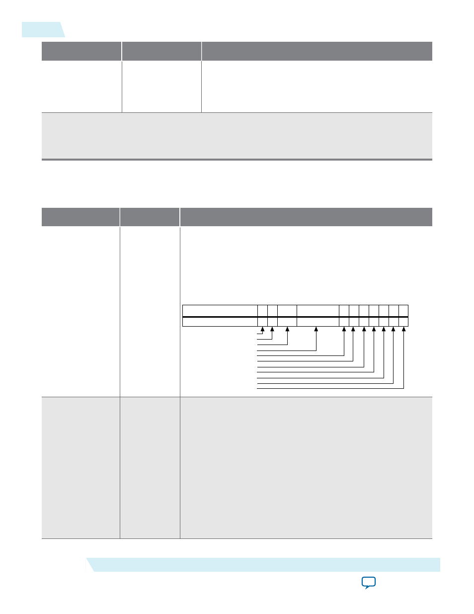
Defines the characteristics of the slot. You turn on this option by
selecting Enable slot capability. The various bits are defined as
follows:
31
19 18 17 16 15 14
7 6 5
Physical Slot Number
No Command Completed Support
Electromechanical Interlock Present
Slot Power Limit Scale
Slot Power Limit Value
Hot-Plug Capable
Hot-Plug Surprise
Power Indicator Present
Attention Indicator Present
MRL Sensor Present
Power Controller Present
Attention Button Present
0
4 3 2 1
Slot power scale
0–3
Specifies the scale used for the Slot power limit. The following
coefficients are defined:
• 0 = 1.0x
• 1 = 0.1x
• 2 = 0.01x
• 3 = 0.001x
The default value prior to hardware and firmware initialization is
b’00. Writes to this register also cause the port to send the
Set_
Slot_Power_Limit
Message.
Refer to Section 6.9 of the PCI Express Base Specification Revision for
more information.
3-12
Slot Capabilities
UG-01145_avmm
2015.05.14
Altera Corporation
Parameter Settings