Sdc timing constraints, Sdc timing constraints -2 – Altera Arria 10 Avalon-MM User Manual
Page 142
entering user mode. Link training occurs after calibration. Refer to Reset Sequence for Hard IP for PCI
Express IP Core and Application Layer for a description of the key signals that reset, control dynamic
reconfiguration, and link training. Altera recommends separate control of reset signals for the Endpoint
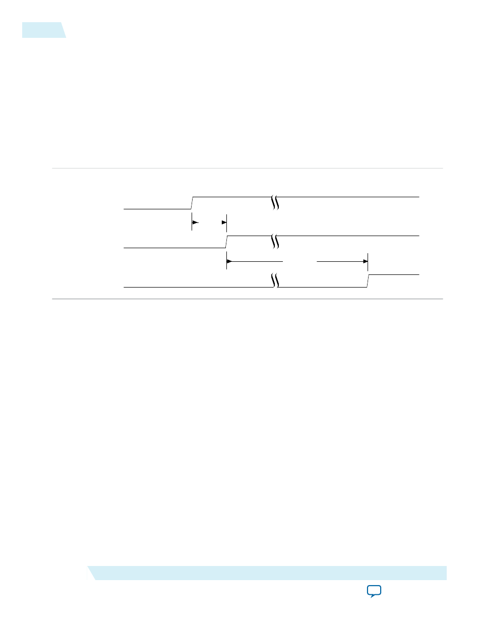
and Root Port. Successful reset sequence includes the following steps:
1. Wait until the FPGA is configured as indicated by the assertion of
CONFIG_DONE
from the FPGA block
controller.
2. Wait 1 ms after the assertion of
CONFIG_DONE
, then deassert the Endpoint reset.
3. Wait approximately 100 ms, then deassert the Root Port reset.
4. Deassert the reset output to the Application Layer.
Figure 11-1: Recommended Reset Sequence
CONF_DONE
Endpoint Reset
Root Port Reset
1 ms
100 ms
Related Information
For information about requirements for the
CLKUSR
pin used during automatic calibration.
SDC Timing Constraints
Your top-level Synopsys Design Constraints file (
.sdc
) must include the following timing constraint macro
for the Arria 10 Hard IP for PCIe IP core.
Example 11-1: SDC Timing Constraints Required for the Arria 10 Hard IP for PCIe and Design
Example
# Constraints required for the Arria 10 Hard IP for PCI Express
# derive_pll_clock is used to calculate all clock derived
# from PCIe refclk. It must be applied once across all
# of the SDC files used in a project
derive_pll_clocks -create_base_clocks
You should only include this constraint in one location across all of the SDC files in your project.
Differences between Fitter timing analysis and TimeQuest timing analysis arise if these
constraints are applied multiple times.
11-2
SDC Timing Constraints
UG-01145_avmm
2015.05.14
Altera Corporation
Design Implementation