B5-04 integral limit setting, B5-06 pi output limit, B5-07 pi offset adjustment – Yaskawa iQpump Controller User Manual User Manual
Page 102
Pump Tuning
102
YASKAWA TM.iQp.06 iQpump Controller User Manual
Table 5.1 PI Setpoint Options
In some situations there are two feedback inputs. The iQpump drive can be programmed to maintain a set differential between two analog
signals. If input A2 is configured as a “PI Differential Mode” (H3-09 = “16: PI Differential”), then the iQpump drive will maintain a set
difference between the measurements read on inputs A1 and A2. This differential setpoint is programmed by parameter (b5-07).
Figure 5.14
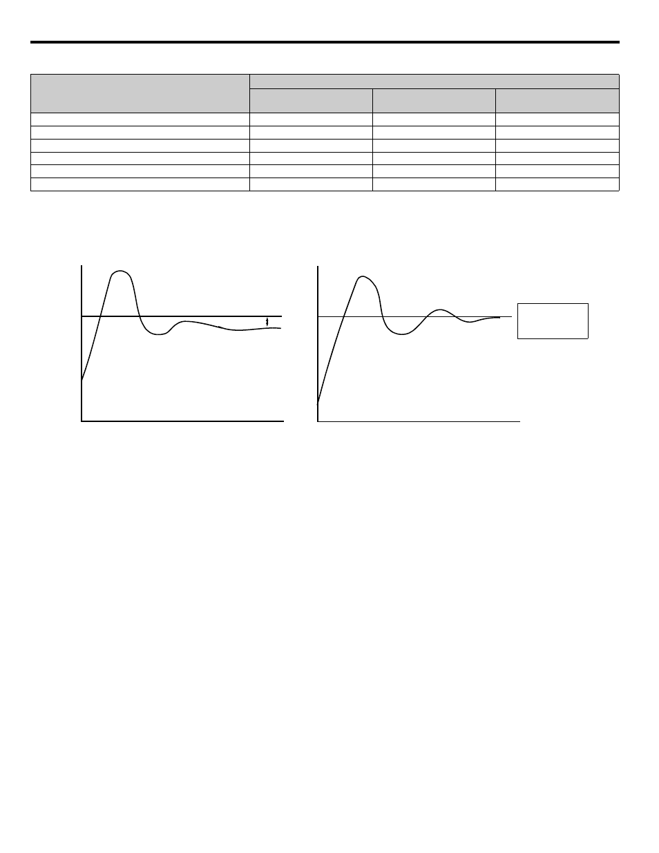
Figure 5.2 PI Feedback Response Characteristics
■
b5-04 Integral Limit Setting
Setting Range: 0.0 ~ 100.0 %
Factory Default: 100.0 %
On some applications, especially those with rapidly varying loads, the output of the PI function may have large oscillations. To suppress
these oscillations, a limit can be applied to the integral factor by programming b5-04.
■
b5-06 PI Output Limit
Setting Range: 0.0 ~ 100.0 %
Factory Default: 100.0 %
Places a cap on the output of the PI function. Limiting the PI function may help to prevent large overshoots in the iQpump drive’s
response to error (the difference between the setpoint and the feedback).
■
b5-07 PI Offset Adjustment
Setting Range: -100.0 % ~ +100.0 %
Factory Default: 0.0 %
The PI Offset Adjustment parameter has two different uses. Parameter b5-07 serves different functions depending on whether it is used
on a Standard PI loop or a Differential PI loop.
Parameter b5-07 causes an offset to be applied to the output of the PI function in a non-Differential PI loop. Every time the PI output is
updated, the offset (b5-07) is summed with the PI output. This can be used to artificially kick-start a slow starting PI loop.
If the iQpump drive is configured for Differential PI Regulation (H3-09 = “16: PI differential”), then this parameter is the target setpoint
for the differential to be maintained between the signal measured on analog input A1 and the signal measured on analog input A2.
The PI Setpoint will be read from:
If these conditions are true
Status of b5-18 =
Status of Modbus
Register 0Fh bit 1
Status of b1-01 =
Parameter b5-19
1
N/A
N/A
Modbus Register 06H
0
ON
N/A
d1-01
0
OFF
0
Terminal A1
0
OFF
1
Serial Comm.
0
OFF
2
Option PCB
0
OFF
3
Zero
offset with
Integral Action
No Integral
With Integral
Me
asur
ed
Fe
edb
ack
Mea
sur
ed Fe
edb
ack
Setpoint
Offset
Setpoint
Feedback
Feedback
TIME
TIME