Duplex system with jockey pump, G.9 iqpump software multiplexing set-up, Figure g.16 with jockey pump wiring diagram – Yaskawa iQpump Controller User Manual User Manual
Page 260
260
YASKAWA
TM.iQp.06 iQpump Controller User Manual
G.9 iQpump Software Multiplexing Set-up
■
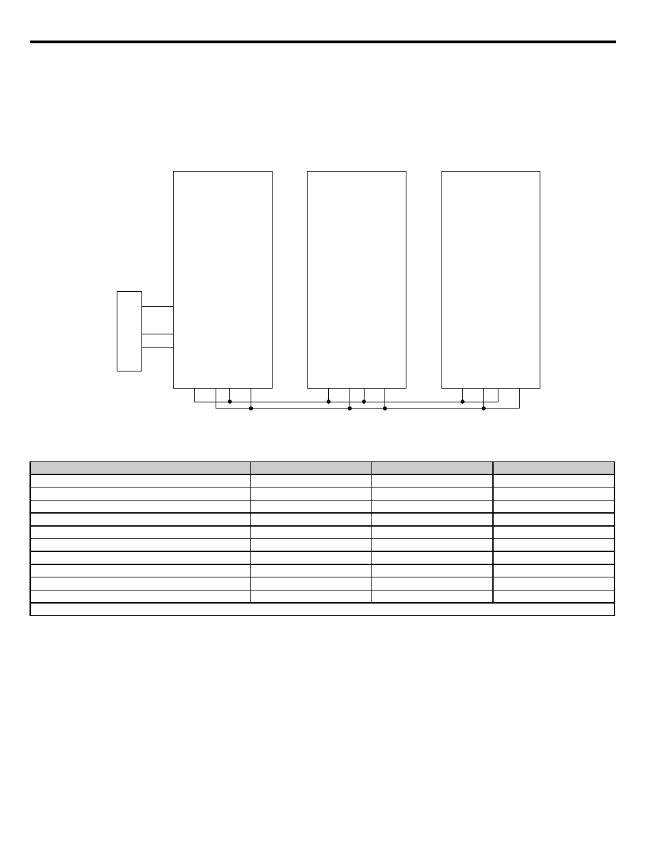
Duplex System with Jockey Pump
A customer requires a pump system with the following requirements:
•
One small pump (the Jockey pump) would run the system during off-peak times.
•
Two larger pumps would run the system when the demand is higher.
• The Jockey pump should not run when the two larger pumps are running.
• Pu
mp wear is still an issue, but it is expected that the small pump will run longer hours and will always run first after a loss of power.
• The feedback scale is 145 psi.
• There is only one feedback transducer in the system.
Figure G.14
Figure G.16 With Jockey Pump Wiring Diagram
Related Parameters for Duplex System with Jockey Pump Example
Description
Jockey Pump
Drive C
Drive D
Node Address
H5-01 = 1
H5-01 = 2
H5-01 = 3
Highest Node Address
P9-25 = 3
P9-25 = 3
P9-25 = 3
Pump Mode: 3 = Network
P1-01 = 3
P1-01 = 3
P1-01 = 3
Feedback Source: 0 = Analog, 3 = Network
P9-02 = 0
P9-02 = 3
P9-02 = 3
Lag Drive Speed: 0 = Always, 2 = Turn Off
P9-05 = 2
P9-05 = 0
P9-05 = 0
Allow Net Run: 0 = Always, 2 = First Only
P9-20 = 2
P9-20 = 0
P9-20 = 0
Run Priority
P9-21 = 7
P9-21 = 8
P9-21 = 8
Lead Swap @ Sleep
P9-24 = 0
P9-24 = 1200 s
P9-24 = 1200 s
Setpoint
U1-01 = 100 psi
U1-01 = 100 psi
U1-01 = 100 psi
Start Level
P1-04 = 80 psi
P1-04 = 80 psi
P1-04 = 80 psi
* All other multiplexing and alternation parameters are at default settings.
(Jockey Pump)
CIMR-P7U47P51-107
R+
S+
S-
R-
A2
AC
+V
A1
SN
S1
Drive B
CIMR-P7U40111-107
R+
S+
S-
R-
A2
AC
+V
A1
SN
S1
SYSTEM PRESSURE
FEEDBACK
Drive C
CIMR-P7U40111-107
R+
S+
S-
R-
A2
AC
+V
A1
SN
S1