Control circuit terminal functions, Wiring checks – Yaskawa iQpump Controller User Manual User Manual
Page 47
2.3 Control Wiring
YASKAWA TM.iQp.06 iQpump Controller User Manual
47
■
Wiring Checks
After all wiring is completed, perform the following checks:
1. Is all wiring correct?
2. Have all wire clippings, screws or other foreign material been removed from the iQpump drive enclosure?
3. Are all terminal screws tight?
◆ Control Circuit Terminal Functions
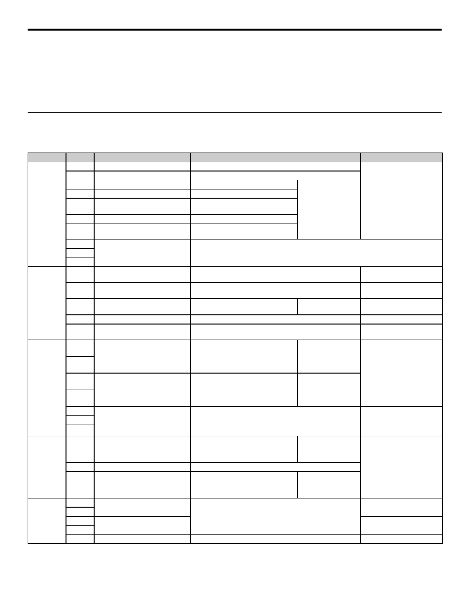
The factory default functions of the control circuit terminals for 2-wire control are shown in
Table 2.8 Control Circuit Terminals
Type
No.
Signal Name
Description
Signal Level
Digital
input
signals
S1
Forward run / stop command
Forward run when CLOSED; stopped when OPEN.
24 Vdc, 8 mA
Photocoupler isolation
S2
Not used.
Not used.
S3
External fault input
Fault when CLOSED.
Multi-function digital
inputs
Functions set by H1-01
to H1-05.
S4
Fault reset
Reset when CLOSED
S5
Multi-step SP1
Multi-step SP1 frequency reference when
CLOSED.
S6
Hand Mode
Hand Mode when CLOSED.
S7
Pre-Charge
Pre-Charge function disabled when
CLOSED.
SN
Digital input common
Refer to
for connection details.
SC
SP
Analog
input
signals
+V
+15 Vdc power supply
+15 Vdc power supply for analog inputs or transmitters
+15 Vdc
(Max. current: 20 mA)
A1
Analog input or
Speed Command
0 to +10 Vdc / 100 %
0 to +10 V (20 k
Ω)
A2
Multi-function analog input
(PI Feedback)
4 ~ 20 mA / 100 %
0 to +10Vdc / 100 % (H3-0
Function set by H3-09.
4 to 20 mA (250
Ω)
0 to +10 V (20 k
Ω)
AC
Analog common
—
—
E(G)
Shield wire, optional ground line
connection point
—
—
Digital output
signals
M1
Pump 2 Control
(N.O. contact)
CLOSED during operation
Multi-function digital
output
Function set by H2-01.
Dry contacts
Contact capacity:
1 A max. at 250 Vac
1 A max. at 30 Vdc
M2
M3
Pump 3 Control
(N.O. contact)
CLOSED when local control
Multi-function digital
output
Function set by H2-02.
M4
MA
Fault output signal
(SPDT)
MA / MC: CLOSED during fault condition
MB / MC: OPEN during fault condition
Dry contacts
Contact capacity:
1 A max. at 250 Vac
1 A max. at 30 Vdc
MB
MC
Analog
output signals
FM
Multi-function analog output
(output frequency)
0 to +10 Vdc / 100 % frequency
Multi-function analog
monitor 1
Function set by H4-01
0 to +10 Vdc max. ±5 %
2 mA max.
AC
Analog common
—
AM
Multi-function analog output
(output current)
0 to +10 Vdc / 100 % drive rated output
current
Multi-function analog
monitor 2
Function set by H4-04
RS-485 /
422
R+
Modbus
communication input
For 2-wire RS-485, jumper R+ and S+ and
jumper R- and S-.
Differential input,
PHC isolation
R-
S+
Modbus
communication output
Differential input,
PHC isolation
S-
IG
Signal common
—
—