O1 monitor configuration, L8-19 overheat frequency reference reduction level, O1-01 user monitor selection – Yaskawa iQpump Controller User Manual User Manual
Page 123: O1-02 power-on monitor

Pump Tuning
YASKAWA TM.iQp.06 iQpump Controller User Manual
123
■
L8-19 Overheat Frequency Reference Reduction Level
Setting Range: 0.0 ~ 100.0 % of maximum frequency
Factory Default: 20.0 % of maximum frequency
When the heatsink temperature reaches the OH Pre-alarm level (L8-02) and the Overheat Pre-Alarm Operation Selection parameter is set
for Alarm and Reduce (L8-03 = “4: OH Alarm and Reduce”), the L8-19 parameter sets the amount of speed decrease that will be applied
to the Speed Command in order to lower the heatsink temperature. The decrease in speed will lower the current being switched and
conducted by the heat producing output transistors of the iQpump drive.
Parameter L8-19 is set in percentage of maximum frequency (E1-04).
◆ o1 Monitor Configuration
■
o1-01 User Monitor Selection
Setting Range: 6 ~ 94
Factory Default: 6
■
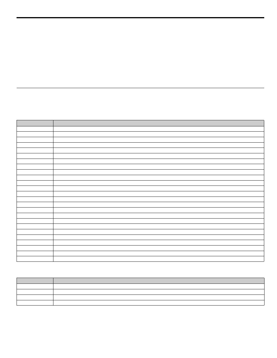
o1-02 Power-On Monitor
When the iQpump drive is powered up, three monitors are displayed on the digital operator. The first and largest monitor is the “Power-
On” monitor. The factory default “Power-On monitor” is Speed Command (U1-01). Below the Speed Command monitor are the next two
sequential monitors, Output Frequency (U1-02) and Output Current (U1-03). Pressing the INCREASE key once scrolls the monitors to
show the User Monitor as selected by o1-01. The factory default for o1-01 is the Output Voltage monitor (U1-06).
Setting
Description
6
Output Voltage (factory default)
7
DC Bus Voltage
8
Output Power
10
Input Terminal Status
11
Output Terminal Status
12
Drive Operation Status
13
Cumulative Operation Time
14
Software Number
15
Terminal A1 Input Voltage
16
Terminal A2 Input Voltage
18
Motor Secondary Current (Iq)
20
Output Frequency After Soft Start
24
PI Feedback Value
28
CPU Number
34
First Parameter Causing an OPE
36
PI Input
37
PI Output
38
PI Setpoint
39
Memobus Communication Error Code
40
Heatsink Cooling Fan Operation Time
90
Pump Setpoint
91
Pump Feedback
92
Pump Status
93
Total Setpoint Compensation
94
Motor Speed
Setting
Description
1
Frequency Reference (factory default)
2
Output Frequency
3
Output Current
4
User Monitor (set by o1-01)