2 iqpump drive quick start-up procedures – Yaskawa iQpump Controller User Manual User Manual
Page 79
4.2 iQpump Drive Quick Start-Up Procedures
YASKAWA TM.iQp.06 iQpump Controller User Manual
79
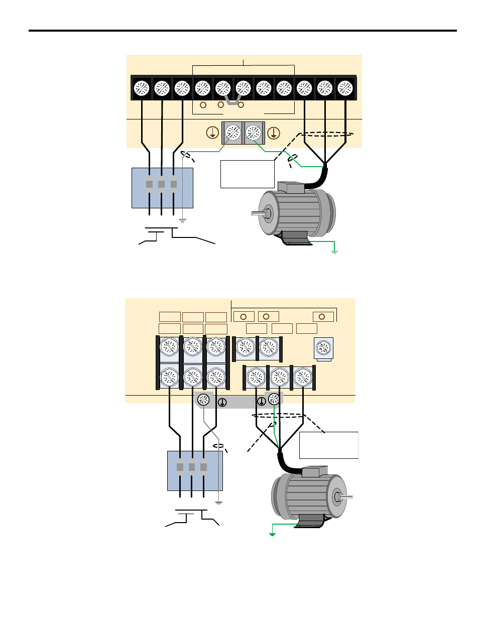
Figure 4.3 Input Power and Output Motor Electrical Connections for Models: 20P4 to 2018 and 40P4 to 4018
Figure 4.4 Input Power and Output Motor Electrical Connections for Models: 2022 & Larger and 4030 & Larger
Note: *Make sure the iQpump drive has been properly sized for single phase input power.
R/L1 S/L2 T/L3
-
+1
+2
B1
B2
U/T1 V/T2 W/T3
NOT USED
3Ø Induction
motor
Use L1, L2, L3 for
3Ø Input Power
Connect
frame to
ground
Input
Protection
(Fuse or Circuit
Breaker )
To change direction of
pump motor rotation
swap any two of the
three motor leads
(See Step 2)
L1 L2 L3
(R/L1)
(S/L2)
(T/L3)
(U/T1)
(V/T2)
(W/T3)
Connect to
chassis
ground
Use L1, L2 for
1Ø Input Power
Connect to
chassis ground
*
NOT USED
3Ø Induction
motor
Connect
frame to
ground
Input
Protection
(Fuse or Circuit
Breaker )
To change direction of pump
motor rotation swap any two
of the three motor leads
(See Step 2)
R/L1
R1/L11
S/L2
S1/L21
T/L3
T1/L31
U/T1
V/T2
W/T3
-
+
1
+
2
(R/L1)
(S/L2)
(T/L3)
(U/T1)
(V/T2)
(W/T3)
Connect to
chassis
ground
Use L1, L2, L3 for
3Ø Input Power
L1 L2 L3
Use L1, L2 for
1Ø Input Power