F.1 electromagnetic compatibility, Electromagnetic compatibility, Introduction – Yaskawa iQpump Controller User Manual User Manual
Page 236: Cable installation, Recommended emc filters
236
YASKAWA
TM.iQp.06 iQpump Controller User Manual
F.1 Electromagnetic Compatibility
F.1
Electromagnetic Compatibility
◆ Introduction
This section describes the measures necessary to comply with the Electromagnetic Compatibility (EMC) Directive. Follow the
installation and wiring instructions in this manual to ensure compliance.
Yaskawa products are tested by authorized organizations using the standards listed below:
Product standard: EN 61800-3:1996
EN 61000-3-2; A1, A2, A14:2000
◆ Measures to Ensure Conformity of Installed Yaskawa Drives to EMC Directive
Yaskawa drives are not required to be installed in a switch cabinet.
It is not possible to give detailed instructions for all possible types of installations, therefore this manual provides general guidelines.
All electrical equipment produces radio and line-borne interference at various frequencies. The power leads pass this on to the
surrounding environment like an antenna. Connecting an item of electrical equipment (e.g. drive) to a supply without a line filter can
allow High Frequency (HF) or Low Frequency (LF) interference to penetrate the power distribution system. The basic countermeasures
are isolation of the wiring of control and power components, proper grounding, and shielding of cables.
A large contact area is necessary for low-impedance grounding of HF interference. The use of grounding, straps instead of cables is
therefore highly recommended.
Cable shields must be connected with ground clips.
◆ Cable Installation
Measures Against Line-Borne Interference:
Line filter and drive must be mounted on the same metal plate. Mount the two components as close to each other as possible, with cables
kept as short as possible (see
Use a power cable with a well-grounded shield. Use a shielded motor cable not exceeding 82 feet (25 m) in length. Arrange all grounds to
maximize the end of the lead area in contact with ground (e.g. metal plate).
Use a shielded cable with braided shield and ground the maximum possible area of the shield. It is advisable to ground the shield by
connecting the cable to the ground plate with metal clips (see
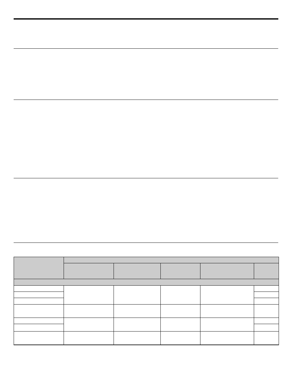
◆ Recommended EMC Filters
Table F.1 Recommended EMC Filters
Drive Model
CIMR-P7U
❑-107
EMC Filter
Model Number
Current Rating
Weight
lb.
(kg)
Dimensions
inches
(mm)
NominalHp
208-240 Vac
20P4
FS5972-10-07
10 A
2.43
(1.1)
5.500 x 13 x 1.875
(141 x 330 x 46)
0.5 / 0.75
20P7
1
21P5
1.5/2
22P2
FS5972-18-07
18 A
2.87
(1.3)
5.500 x 13 x 1.875
(141 x 330 x 46)
3
23P7
FS5973-35-07
35 A
3.09
(1.4)
5.500 x 13 x 1.875
(141 x 330 x 46)
5
25P5
7.5
27P5
FS5973-60-07
60 A
6.61
(3)
8 x 14 x 2.375
(206 x 355 x 60)
10