Setpoint potentiometer – Yaskawa iQpump Controller User Manual User Manual
Page 92
5.1 iQpump Drive Basic Programming Parameters
92
YASKAWA TM.iQp.06 iQpump Controller User Manual
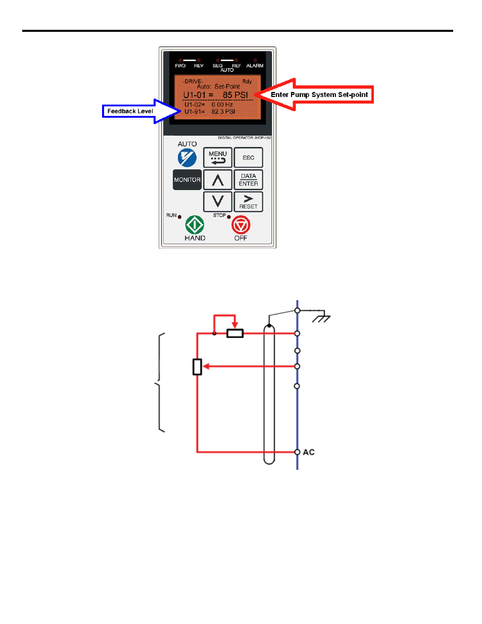
Figure 5.2
Figure 5.2 Digital Operator Auto Setpoint
If you want the iQpump drive to follow an “Auto Setpoint” set by the analog input: Set b1-01 = “1: Terminals,” and connect a
potentiometer or external signal to the iQpump drive. Refer to
for connection diagram for the setpoint potentiometer.
Figure 5.3 Setpoint Potentiometer Connection Diagram
Refer to
for the connection diagram for an external analog signal setpoint reference.
Note: When b1-01 = 1 (terminals) and P5-01 = 0 (hand mode reference source), the setpoint and the hand reference are
determined by the external analog signal.
Setpoint
Potentiometer
+V +15 Vdc +/- 10 %, 20 mA
A1 0 to +/- 10 Vdc, 20 kΩ
Ω*
2 kΩ
2 kΩ
E (G)