H3-08 terminal a2 signal level – Yaskawa iQpump Controller User Manual User Manual
Page 112
Pump Tuning
112
YASKAWA TM.iQp.06 iQpump Controller User Manual
Figure 5.21
Figure 5.36 Output Frequency with Reduced Bias Setting
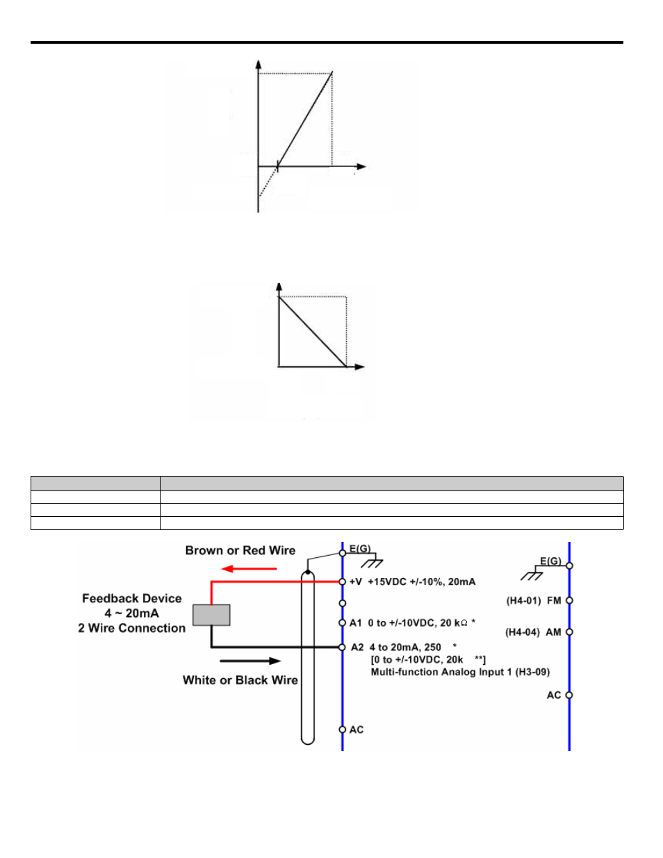
As a further example, for an inverse-acting speed command, set the bias = 100 % and the gain = 0 %. The minimum analog input level (0
Vdc or 4 mA) will produce a 100 % speed command and the maximum analog input level (10 Vdc or 20 mA) will produce a 0 % speed
command.
Figure 5.22
Figure 5.37 Output Frequency with Inverted Gain and Bias Settings
■
H3-08 Terminal A2 Signal Level
Figure 5.23
Figure 5.38 Connection of a 2-Wire 4~20 mA Feedback Device (H3-08 = 2)
Setting
Description
0
0 - 10 Vdc
2
4 ~ 20 mA (factory default)
3
0 - 20 mA
Analog Input Signal
Gain = 100 %
Bias = -25 %
0 V
4 mA
Analog Input Signal
Ou
tp
u
t
Fr
e
q
u
e
n
c
y
2.5 V
8 mA
10 V
20 mA
Analog I nput Signal
Bias
Gain
10 V
20 mA
Gain = 0 %
Bias = 100 %
0 V
4 mA
Analog Input Signal
Ou
tp
u
t
F
requenc
y