D.3 modbus data tables, Modbus data tables, Reference data – Yaskawa iQpump Controller User Manual User Manual
Page 220

220
YASKAWA
TM.iQp.06 iQpump Controller User Manual
D.3 Modbus Data Tables
D.3 Modbus Data Tables
The data tables are shown below. The types of data are as follows: Reference data, monitor data and broadcast data.
◆ Reference Data
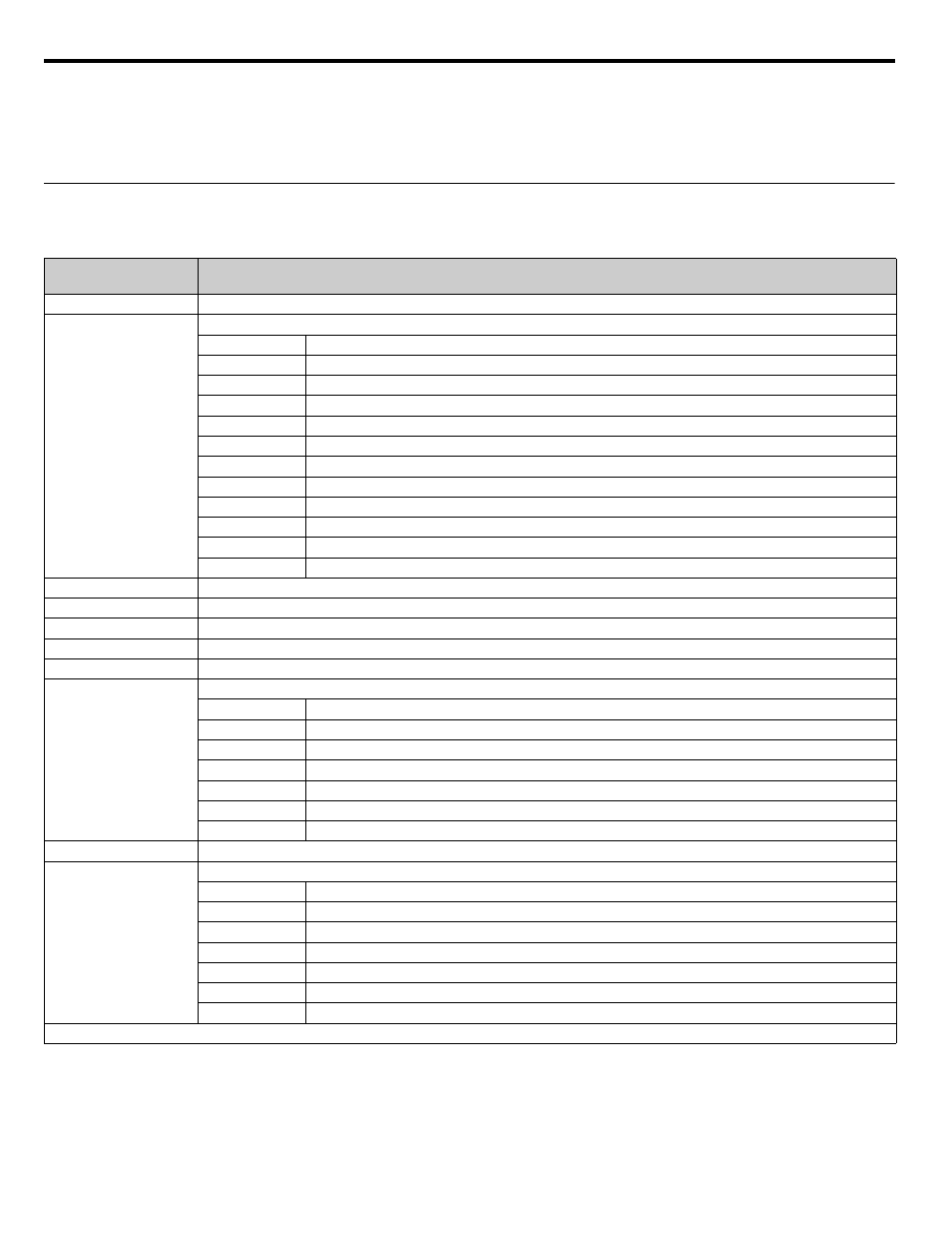
The reference data table is shown below. Reference data can be read and written to.
Table D.6 Reference Data
Register No.
(Hex)
Contents
0000
Reserved
0001
Frequency reference
Bit 0
Run Forward 1: Run Forward
Bit 1
Run Reverse 1: Run Reverse
Bit 2
External fault 1: Fault (EFO)
Bit 3
Fault reset 1: Reset command
Bit 4
ComNet
Bit 5
ComCtrl
Bit 6
Multi-function digital input command 3
Bit 7
Multi-function digital input command 4
Bit 8
Multi-function digital input command 5
Bit 9
Multi-function digital input command 6
Bit A
Multi-function digital input command 7
Bits B to F
Not used
0002
Frequency reference (Set units using parameter o1-03)
0003 to 0005
Not used
0006
PI Setpoint
0007
Analog output 1 setting (-11 V = 726 to 11 V = 726)
→ 10 V = 660
0008
Analog output 2 setting (-11 V = 726 to 11 V = 726)
→ 10 V = 660
0009
Multi-function contact output setting
Bit 0
Digital output 1 (Terminal M1-M2) 1: ON 0: OFF
Bit 1
Digital output 2 (Terminal M3-M4) 1: ON 0: OFF
Bit 2
Not Used
Bits 3 to 5
Not used
Bit 6
Set fault contact (terminal MA-MC) output using bit 7. 1: ON 0: OFF
Bit 7
Fault contact (terminal MA-MC) 1: ON 0: OFF
Bits 8 to F
Not used
000A to 000E
Not used
000F
Reference selection settings
Bit 0
Not used
Bit 1
Input PI setpoint 1: Enabled 0: Disabled
Bits 3 to B
Not used
C
Broadcast data terminal S5 input 1: Enabled 0: Disabled
D
Broadcast data terminal S6 input 1: Enabled 0: Disabled
E
Broadcast data terminal S7 input 1: Enabled 0: Disabled
F
Not used
Write 0 to all unused bits. Also, do not write data to reserved registers.