C1 accel / decel, D2 reference (speed command) limits – Yaskawa iQpump Controller User Manual User Manual
Page 105
Pump Tuning
YASKAWA TM.iQp.06 iQpump Controller User Manual
105
◆ C1 Accel / Decel
■
C1-01 Acceleration Time 1
C1-02 Deceleration Time 1
C1-03 Acceleration Time 2
C1-04 Deceleration Time 2
C1-05 Acceleration Time 3
C1-06 Deceleration Time 3
Setting Range: 0.0 ~ 6000.0 s
Factory Default: C1-01 20.0 s
Factory Default:
C1-02, C1-03 and C1-04, 10.0 s
Fa tory Defau lt:
C1-05 and C1-06, 50.0 s
C1-01 (Acceleration Time 1) sets the time to accelerate from zero to maximum speed (E1-04). C1-02 (Deceleration Time 1) sets the time
to decelerate from maximum speed to zero. C1-01 and C1-02 are the factory default active accel / decel “pair.” Another accel / decel pair
(C1-03 and C1-04) exists that can be activated by a multi-function digital input (H1-0x = 7), or specified by a switch over frequency as
programmed in parameter C1-11.
The C1-05 (Acceleration Time 3) and C1-06 (Deceleration Time 3) are used during the multiple pumping operation. Refer to P3-12 (in
the Programming Manual) for further description.
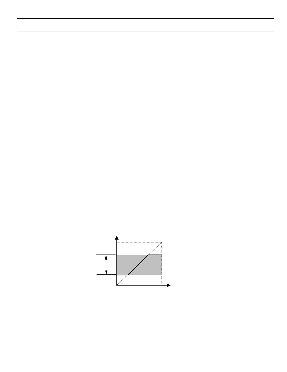
◆ d2 Reference (Speed Command) Limits
■
d2-01 Frequency Reference Upper Limit
Setting Range: 0.0 ~ 110.0 %
Factory Default: 100.0 %
■
d2-02 Frequency Reference Lower Limit
Setting Range: 0.0 ~ 110.0 %
Factory Default: 0.0 %
The use of parameters d2-01 and d2-02 places limitations on the speed command that the iQpump drive will accept. The parameters are
set in units of percentage of the maximum frequency (E1-04) and provide limits on any remote speed command input. By entering upper
or lower frequency limits, the iQpump drive programmer can prevent operation of the iQpump drive above or below levels that may
cause resonance, equipment damage or discomfort (see also parameter d3-0x). For example, limits may be needed to prevent low speed
operation of: Cooling tower fans with gear boxes, pumps with pressure dependent seals, or AHUs with minimum delivery requirements.
Figure 5.16
Figure 5.4 Frequency Reference Upper and Lower Limit Effects on the Speed Command
d2-01
d2-02
Frequency Reference Upper Limit
Frequency Reference Lower Limit
Internal Speed Command
Set Speed Command
d2-01
d2-02
Operating
Range