Step # 3 - control wiring, Select start / stop control method, Feedback signal wiring (transducer) – Yaskawa iQpump Controller User Manual User Manual
Page 80: 2 iqpump drive quick start-up procedures, Figure 4.6 feedback signal wiring (transducer)
4.2 iQpump Drive Quick Start-Up Procedures
80
YASKAWA TM.iQp.06 iQpump Controller User Manual
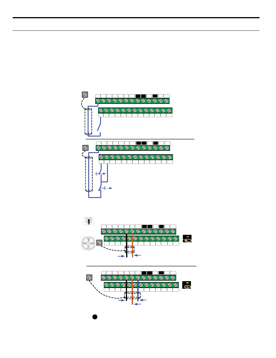
◆ Step # 3 - Control Wiring
This step shows how to connect control wiring and feedback signal to the iQpump
WARNING! Before making any control connections, turn off power to the iQpump drive! Serious injury or death
may occur by electrocution.
Next remove the terminal cover to gain access to the control terminals (Step 1).
■
Select Start / Stop Control Method
The iQpump drive is set to START/STOP FROM THE KEYPAD (digital operator) as the factory default. If this is the preferred start/stop
method, then continue to the feedback signal connection section. Please refer to
to start/stop the iQpump using an external
switch or contact.
Figure 4.5 Select Start / Stop Control Method
■
Feedback Signal Wiring (Transducer)
Figure 4.6 Feedback Signal Wiring (Transducer)
S3
S5 S6 S7 FM AC AM IG
S2
S4
S1
2-Wire Control
Use for permanent contacts
iQpump User Control Terminals
S+
S-
SP
A2 +V AC
AC
SC
A1
SN
R+ R-
Connect switch or contact to
terminal S 1 and terminal SN
S3
S5 S6 S7 FM AC AM IG
S2
S4
S1
Use for momentary contacts
S+ S-
SP
A2 +V AC
AC
SC
A1
SN
R+ R-
Connect momentary contacts
to terminal S 1, S2 and SN
Normally Open
Normally Closed
To use 3-Wire Control first
initialize the iQpump using
parameter A1-03 = 3330
(Refer to TM .iQp.01)
Cable
Shield
Cable
Shield
E(G)
S3
S5 S6 S7 FM AC AM IG
S2
S4
S1
For use with 3-Wire, 0 – 10V Transducer
iQpump User Control Terminals
S+ S-
SP
A2 +V AC
AC
SC
A1
SN
R+ R-
Brown or Red : +Power (1)
O
F
F
1
2
S1-2 in ON
Position
S3
S5 S6 S7 FM AC AM IG
S2
S4
S1
S+ S-
SP
A2 +V AC
AC
SC
A1
SN
R+ R-
Brown or Red: +Power (1)
Black or White Output
0 – 10V (3)
O
F
F
1
2
S1-2 in OFF
Position
Blue or Black
Common Signal (2)
Black: Output
4 – 20mA (2)
Cable
Type
DIN
Type
For use with 2-Wire, 4 – 20mA Transducer
Important Note : Signal colors and numbering may
vary depending on feedback device used .
Please consult feedback device manual .
!
E(G)
(Factory Default )
E(G)
Cable
Shield
Cable
Shield