L2 momentary power loss ride-thru function – Yaskawa iQpump Controller User Manual User Manual
Page 116
Pump Tuning
116
YASKAWA TM.iQp.06 iQpump Controller User Manual
■
H3-11 Terminal A2 Bias Setting
Setting Range:
–
100.0 % ~ +100.0 %
Factory Default: 0.0 %
Parameters H3-10 and H3-11 perform the same function for the A2 analog input that parameters H3-02 and H3-03 perform for the A1
analog input. Please refer to the parameter description for H3-02 and H3-03 for information about H3-10 and H3-11.
These parameters could be used for final calibration of a factory or field installed pressure to electric transducer input
connected to terminal A2 and AC. This field calibration may be needed if there is a job site variation from the typical 3 to 15 psiG
pneumatic signal input range.
■
H3-12 Analog Input Filter Time Constant
Setting Range: 0.00 ~ 2.00 s
Factory Default: 0.30 s
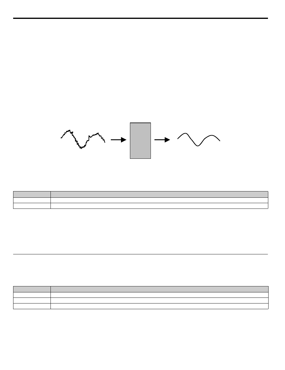
An analog input filter can be used to prevent erratic iQpump drive control when a “noisy” analog reference is used. Parameter H3-12 sets
the time constant for a first order filter that will be applied to both the A1 and A2 analog inputs. The iQpump drive operation becomes
more stable the longer the time programmed, but it becomes less responsive to rapidly changing analog signals.
Figure 5.27
Figure 5.44 Analog Input Filter Time Constant Effect on “Noisy” Signal
■
H3-13 Master Frequency Reference Terminal Selection
Parameter H3-13 allows the programmer to select which analog input will serve as the Speed Command input when “Terminals” are
selected as the Auto Mode Speed source (b1-01 = “1: Terminals”), or Terminal is selected as the reference source for the Hand mode (b1-
12 = “1: Terminals”). For the A2 analog input to be an effective selection for the H3-13 parameter, parameter H3-09 must be configured
as Aux Reference (H3-09 = “2: Aux Reference”).
If H3-09
≠
2, then the A1 analog input will be used regardless of the setting of parameter b1-12.
◆ L2 Momentary Power Loss Ride-Thru Function
When momentary power loss recovery is enabled (L2-01
≠
0), a speed search is executed to catch the potentially spinning motor shaft.
This speed search will occur regardless of the setting of b3-01 “Speed Search Selection.”
■
L2-01 Momentary Power Loss Detection Selection
Setting
Description
0
Main Fref = A1 (factory default)
1
Main Fref = A2
Setting
Description
0
Disabled
1
PwrL Ride Thru t
2
CPU Power Active (factory default)
Analog
Input
Filter
Noisy
input
signal
Analog
input post
Internal Analog Input Valve
(Filtered)