Triplex system, G.9 iqpump software multiplexing set-up, Figure g.17 triplex system wiring diagram – Yaskawa iQpump Controller User Manual User Manual
Page 261
G.9 iQpump Software Multiplexing Set-up
YASKAWA
TM.iQp.06 iQpump Controller User Manual
261
■
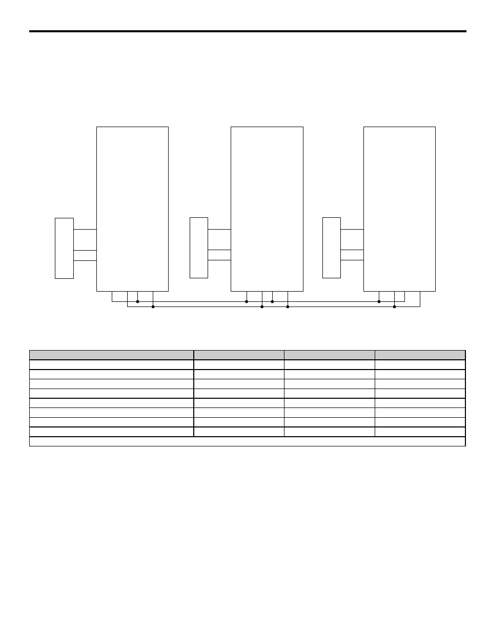
Triplex System
A customer who currently runs a duplex system would like to retrofit an existing triplex system with the following requirements:
•
Three similarly sized pumps would run the system.
• A maximum of two iQpump drives should be running at any point; the third iQpump drive is a back-up.
• Alternation should only happen when pumps are not running (sleeping).
•
If one of the analog pressure feedback transducers should fail, read from a working one and notify the customer of the failure by the alarm display.
• Setpoint is 90 psi, feedback scale is 145 psi, start level is 75 psi.
Figure G.15
Figure G.17 Triplex System Wiring Diagram
Related Parameters for Triplex System Example
Description
Drive A
Drive B
Drive C
Node Address
H5-01 = 1
H5-01 = 2
H5-01 = 3
Highest Node Address
P9-25 = 3
P9-25 = 3
P9-25 = 3
Pump Mode: 3 = Network
P1-01 = 3
P1-01 = 3
P1-01 = 3
Feedback Source: 2= Analog ->Net, with Alarm
P9-02 = 2
P9-02 = 2
P9-02 = 2
Alternation Mode: 3 = FIFO @ Sleep
P9-04 = 3
P9-04 = 3
P9-04 = 3
Maximum Running Pumps
P9-23 = 2
P9-23 = 2
P9-23 = 2
Setpoint
U1-01 = 90 psi
U1-01 = 90 psi
U1-01 = 90 psi
Start Level
P1-04 = 75.0 psi
P1-04 = 75.0 psi
P1-04 = 75.0 psi
* All other multiplexing and alternation parameters are at default settings.
Drive A
CIMR-P7U40181-107
R+
S+
S-
R-
A2
AC
+V
A1
SN
S1
Drive B
CIMR-P7U40181-107
R+
S+
S-
R-
A2
AC
+V
A1
SN
S1
SYSTEM PRESSURE
FEEDBACK
Drive C
CIMR-P7U40181-107
R+
S+
S-
R-
A2
AC
+V
A1
SN
S1
SYSTEM PRESSURE
FEEDBACK
SYSTEM PRESSURE
FEEDBACK