B5-08 pi primary delay time constant, B5-09 pi output level selection, B5-10 pi output gain setting – Yaskawa iQpump Controller User Manual User Manual
Page 103: B5-13 pi feedback loss detection level, B5-14 pi feedback loss detection time
Pump Tuning
YASKAWA TM.iQp.06 iQpump Controller User Manual
103
■
b5-08 PI Primary Delay Time Constant
Setting Range: 0.00 ~ 10.00 s
Factory Default: 0.00 s
Acts as a time based filter that lowers the responsiveness of the PI function, but also makes the function more stable when the setpoint
varies rapidly or when the feedback is noisy.
■
b5-09 PI Output Level Selection
Normally, the output of the PI function causes an increase in motor speed whenever the measured feedback is below the setpoint. This is
referred to as direct acting response. However, if b5-09 = “1: Reverse Output,” the output of the PI function causes the motor to slow
down when the feedback is below the setpoint. This is referred to as reverse acting response.
■
b5-10 PI Output Gain Setting
Setting Range: 0.0 ~ 25.0
Factory Default: 1.0
Applies a multiplier to the output of the PI function. Using the gain can be helpful when the PI function is used to trim the Speed
Command. Increasing b5-10 causes the PI function to have a greater regulating affect on the speed command.
■
b5-12 PI Feedback Reference Missing Detection Selection
Loss of feedback can cause problems to a PI application. The iQpump drive can be programmed to turn on a digital output whenever a
loss of feedback occurs. Feedback Loss Detection is turned on by b5-12. When b5-12 = “1: Alarm,” the iQpump drive acknowledges the
loss of feedback without stopping or turning on the fault output (MA-MB). If b5-12 = “2: Fault,” the iQpump drive coasts to a stop and
turns on the fault output if the feedback is determined to be lost.
■
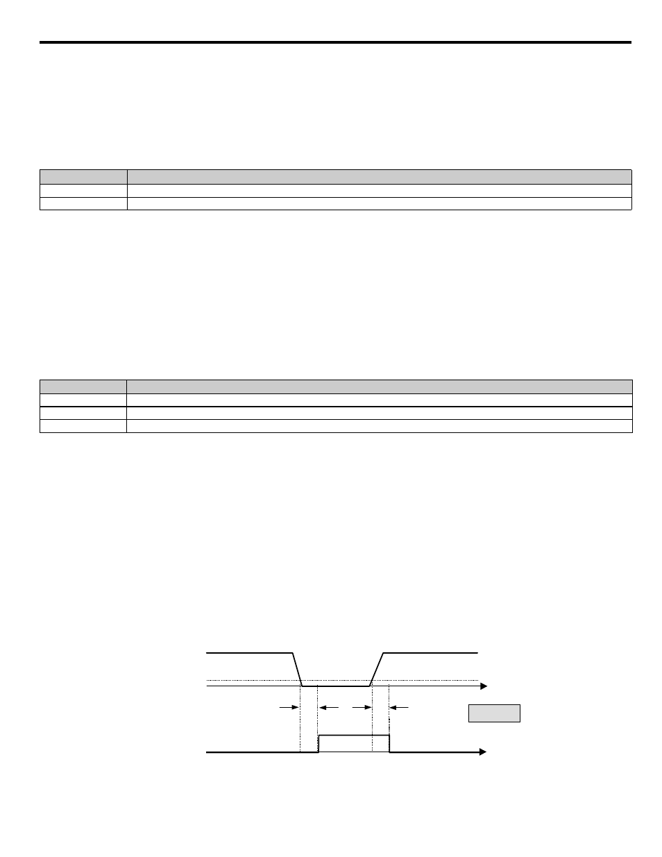
b5-13 PI Feedback Loss Detection Level
Setting Range: 0 ~ 100 %
Factory Default: 0 %
■
b5-14 PI Feedback Loss Detection Time
Setting Range: 0.0 ~ 25.0 s
Factory Default: 2.0 s
The iQpump drive interprets feedback loss whenever the feedback signal drops below the value of b5-13 and stays below that level for at
least the time set into b5-14. See
for timing details.
Figure 5.15
Figure 5.3 Loss of PI Feedback Feature
Setting
Description
0
Normal Output (direct acting) (factory default)
1
Reverse Output (reverse acting)
Setting
Description
0
Disabled
1
Alarm
2
Fault (factory default)
Measured
Feedback
T
t
Feedback
Loss Output
T
b5-13
T = b5-14
Feedback
Loss Digital Output
ON (CLOSED)
OFF (OPEN)
TIME