Yaskawa iQpump Controller User Manual User Manual
Page 32
1.9 Removing/Attaching the Digital Operator and Front Cover
32
YASKAWA TM.iQp.06 iQpump Controller User Manual
◆ Models CIMR-P7U2022 through 2110 (30 HP to 150 HP @ 208 V / 240 V) and
4030 through 4300 (40 HP to 500 HP @ 480 V)
For Models CIMR-P7U2022 / 4030-107 and larger, remove the terminal cover and then use the following procedures to remove the
Digital Operator and front cover.
■
Removing the Digital Operator
Use the same procedure for Models CIMR-P7U2018 / 4018-107 and smaller.
■
Removing the Front Cover
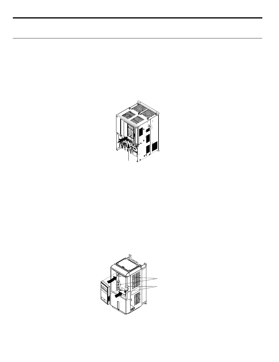
Loosen all screws on the front cover. Lift up at the location labeled 1 at the top of the control circuit terminal card and move in the
direction of arrow 2.
Figure 1.17 Removing the Front Cover
■
Attaching the Front Cover
Attach the front cover by reversing the procedure to remove it.
1. Confirm that the digital operator is not mounted on the front cover. Contact faults can occur if the cover is attached while the digital
operator is mounted to it.
2. Insert the tab on the top of the front cover into the slot on the iQpump drive and press in on the cover until it snaps into place on the
iQpump drive.
■
Attaching the Digital Operator
After attaching the front cover, mount the digital operator onto the iQpump drive using the following procedure.
1. Hook the digital operator at A (two locations) on the front cover by moving in the direction of arrow 1 as shown in the following
illustration.
2. Press the digital operator in the direction of arrow 2 until it snaps in place at B (two locations).
Figure 1.18 Mounting the Digital Operator
1
2
A
B
1
2