Yaskawa iQpump Controller User Manual User Manual
Page 223

D.3 Modbus Data Tables
YASKAWA
TM.iQp.06 iQpump Controller User Manual
223
Broadcast Data
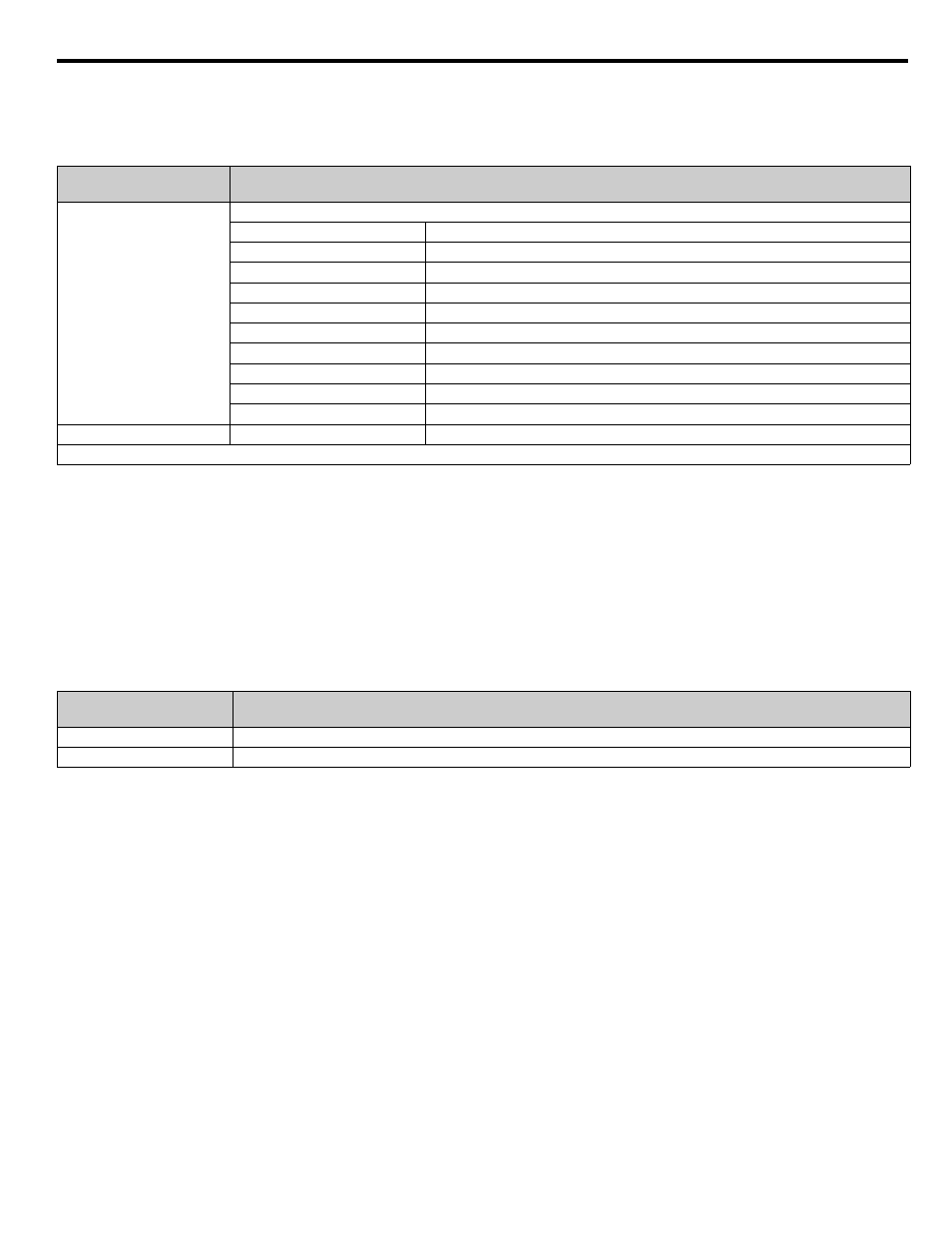
The following table shows the broadcast data. Broadcast data can be written to.
Table D.8 Broadcast Data
Enter Command
When writing parameters to the drive from the PLC using Modbus communication, the parameters are temporarily stored in the constant
data area in the drive. To enable these parameters in the parameter data area, use the Enter command.
There are two types of Enter commands:
1. 1. Enter commands that enable parameter data in RAM
2. 2. Enter commands that write data to EEPROM (non-volatile memory) in the drive at the same time as enabling data in RAM.
The following table shows the Enter command data. Enter command data can only be written.
The Enter command is enabled by writing 0 to register number 0900 H or 0901 H.
Table D.9 Enter Command
IMPORTANT: The maximum number of times you can write to EEPROM using the drive is 100,000. Do not frequently execute Enter
commands (0900) written to EEPROM. The Enter command registers are write-only. Consequently, if reading these registers, the register
address will become invalid (Error code: 02 H).
Register Address
(Hex)
Contents
0001
Operation signal
Bit 0
Run command 1: Operating 0: Stopped
Bit 1
Reverse operation command 1: Reverse 0: Forward
Bits 2 and 3
Not used
Bit 4
External error 1: Fault (set using H1-01)
Bit 5
Error Fault 1: Reset command (set using H1-02)
Bits 6 to B
Not used
Bit C
Multi-function digital input terminal S5 input
Bit D
Multi-function digital input terminal S6 input
Bit E
Multi-function digital input terminal S7 input
Bit F
Not used.
0002
Frequency reference
30000 / 100%
Note: Bit signals not defined in the broadcast operation signals use local node data signals continuously.
Register No.
(Hex)
Contents
0900
Write parameter data to EEPROM
0910
Parameter data is not written to EEPROM, but refreshed in RAM only.