8 removing and attaching the terminal cover, Removing and attaching the terminal cover, Removing the terminal cover – Yaskawa iQpump Controller User Manual User Manual
Page 30: Attaching the terminal cover
1.8 Removing and Attaching the Terminal Cover
30
YASKAWA TM.iQp.06 iQpump Controller User Manual
1.8
Removing and Attaching the Terminal Cover
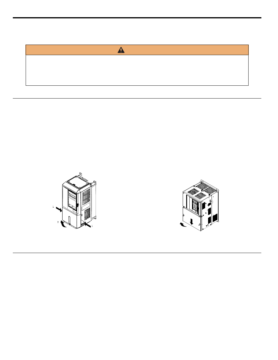
Remove the terminal cover to connect cables to the control circuit and main circuit terminals.
◆ Removing the Terminal Cover
■
Models CIMR-P7U20P4 through 2018 (0.5 HP to 25 HP @ 208 V / 240 V) and 40P4 through 4018
(0.5 HP to 30 HP @ 480 V)
Loosen the screw at the bottom of the terminal cover, press in on the sides of the terminal cover in the directions of arrows 1, and then lift
up on the terminal in the direction of arrow 2. Refer to
.
■
Models CIMR-P7U2022 through 2110 (30 HP to 150 HP @ 208 V / 240 V) and 4030 through 4300
(40 HP to 500 HP @ 480 V)
Loosen the screws on the left and right at the top of the terminal cover, pull down the terminal cover in the direction of arrow 1 and then
lift up on the terminal cover in the direction of arrow 2. Refer to
Figure 1.1
◆ Attaching the Terminal Cover
After wiring the terminal block, attach the terminal cover by reversing the removal procedure.
For Models CIMR-P7U2018 / 4018-107 and smaller, insert the tab on the top of the terminal cover into the groove on the iQpump drive
and press in on the bottom of the terminal cover until it snaps into place.
For iQpump drives CIMR-P7U2022 / 4030-107 and larger, insert the tab on the top of the terminal cover into the groove on the iQpump
drive, and secure the terminal cover by lifting it up toward the top of the iQpump drive.
WARNING
Prior to removing any protective cover or wiring any part of the iQpump drive, remove all power sources, including
main input power and control circuit power. Wait a minimum 5 minutes after power removal, before removing any cover.
The charge lamp located within the iQpump drive should be off prior to working inside. Even if the charge lamp is off,
one must measure the AC input, output, and DC Bus potential to insure safe levels prior to resuming work. Failure to
adhere to this warning may result in personal injury or death.
Figure 1.13 Removing the Terminal Cover
Figure 1.14 Removing the Terminal Cover
1
2